Computer to Radio Interfacing
100 likes | 138 Views
Learn how to set up a very simple interface between a computer and a Ten-Tek Omni 6 Plus radio using RS-232 communication. Explore how the N2FJP Logging Program can send commands to the transceiver and display operating frequencies, modes, and bands. Discover the command format for interacting with the Ten-Tek radio and sending data codes. Master the process of interfacing the computer and radio seamlessly for enhanced functionality.

Computer to Radio Interfacing
E N D
Presentation Transcript
Computer to Radio Interfacing May 14, 2012
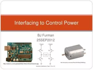
A Very Simple Interface Procedure! Radio with RS-232 Interface Computer Running a Terminal Program
The Rig we’ll use is the Ten-Tek Omni 6 Plus Reasons are: Large easy to see readouts Straightforward RS-232 I/O Easy to carry The Terminal we’ll use is the N2FJP Logging Program Reasons are: We will use it at Kids Day and at Field Day It is more or less intuitive to operate It has only a limited range of capabilities.
The communication capability built into the Logging Program can: Send a code to the transceiver asking it to return a code with it’s operating frequency, and the program will put that frequency on the working screen. Send a code to the transceiver asking it to return a code with it’s operating mode (CW or PH), and then put the answer on the screen and into the log. Send a code to the transceiver asking it to return a code with it’s operating band, and then put the answer on the screen and into the log. Send various other codes to the transceiver ordering it to change one of it’s operating parameters (frequency, mode, filter bandwidth, etc.), and then expecting an answer from the transceiver which indicates the order has been performed (not performed).
In the case of the Ten-Tek the codes are Packets, having variable lengths depending on what is being asked for or what it is being commanded to do…. BUT The Packets always have: a Start Signal (like CQ), a set of addresses (K2JV this is K2AL), an action command (QSY), a set of data codes (such as “145.750”), and an End Signal (over or out). The Ten-Tek is a simple “Slave System” and does not originate Commands on it’s own, so… The Computer (Master) must “Poll” the transceiver regularly in order to stay up to date on it’s activity.
The General Command Format When the Computer calls the Transceiver Start Code Calling Ten-Tek This is the Computer Do This… Use This… End of Message Address - 04h Address = E0h There are about 20 Command and Response codes which the Ten-Tek will recognize. A few of them are listed below, the first three are the ones used by the logging program:
There are also a bunch of Data Codes which represent the operating conditions of the rig Modes Filters And then there is the case when you need to send frequencies as decimal numbers The computer will parse them out into 5 bytes encoded as BCD digits -- OY Vay! And worse, the bytes are sent in reverse order, least significant numbers first. For example… 7.156.25 is sent as 50 62 15 07 00
A Simple Command Sent Repeatedly to the Transceiver The spaces are put in by the computer which Parses the codes into 2 byte words: FE FE 04 E0 03 FD FE FE E0 04 03 20 64 24 07 00 FD Answer: I’m on 7.246.42 MHz Start - Ten-Tec de Computer What Freq? EOM Another Simple Command FE FE 04 E0 04 FD FE FE E0 04 04 00 02 FD What Mode are you in? I’m in Mode 0 (LSB) and using Filter #2 (2,4 kHz)