interfacing
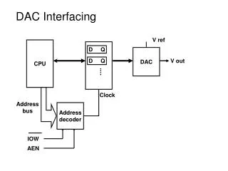
interfacing. rd'/wr. Processor. Memory. enable. addr[0-11]. data[0-7]. bus. bus structure. A simple bus. Wires: Uni-directional or bi-directional One line may represent multiple wires Bus Set of wires with a single function Address bus, data bus Or, entire collection of wires


interfacing
E N D
Presentation Transcript
rd'/wr Processor Memory enable addr[0-11] data[0-7] bus bus structure A simple bus • Wires: • Uni-directional or bi-directional • One line may represent multiple wires • Bus • Set of wires with a single function • Address bus, data bus • Or, entire collection of wires • Address, data and control • Associated protocol: rules for communication
rd'/wr Processor Memory port enable addr[0-11] data[0-7] Ports • Conducting device on periphery • Connects bus to processor or memory • Often referred to as a pin • Actual pins on periphery of IC package that plug into socket on printed-circuit board • Sometimes metallic balls instead of pins • Today, metal “pads” connecting processors and memories within single IC • Single wire or set of wires with single function • E.g., 12-wire address port bus
rd'/wr enable addr data tsetup tread read protocol rd'/wr enable addr data tsetup twrite write protocol Timing Diagrams • Most common method for describing a communication protocol • Time proceeds to the right on x-axis • Control signal: low or high • May be active low (e.g., go’, /go, or go_L) • Use terms assert (active) and deassert • Asserting go’ means go=0 • Data signal: not valid or valid • Protocol may have subprotocols • Called bus cycle, e.g., read and write • Each may be several clock cycles • Read example • rd’/wr set low,address placed on addr for at least tsetup time before enable asserted, enable triggers memory to place data on data wires by time tread
Time-multiplexed data transfer Master Servant Master Servant req req 7:0 15:8 data(15:0) data(15:0) addr data addr data mux demux mux demux data(8) addr/data req req data addr/data data serializing address/data muxing addr data Basic protocol concepts • Actor: master initiates, servant (slave) respond • Direction: sender, receiver • Addresses: special kind of data • Specifies a location in memory, a peripheral, or a register within a peripheral • Time multiplexing • Share a single set of wires for multiple pieces of data • Saves wires at expense of time
Master Servant Master req Servant req ack data data req 1 3 req 1 3 ack 2 4 data 2 4 data taccess 1. Master asserts req to receive data 1. Master asserts req to receive data 2. Servant puts data on bus within time taccess 2. Servant puts data on bus and asserts ack 3. Master receives data and deasserts req 3. Master receives data and deasserts req 4. Servant ready for next request 4. Servant ready for next request Strobe protocol Handshake protocol Basic protocol concepts: control methods
Master Servant req wait data req 1 3 req 1 4 wait wait 2 3 data 2 4 data 5 taccess taccess 1. Master asserts req to receive data 1. Master asserts req to receive data 2. Servant puts data on buswithin time taccess 2. Servant can't put data within taccess, asserts wait ack (wait line is unused) 3. Servant puts data on bus and deasserts wait 3. Master receives data and deasserts req 4. Master receives data and deasserts req 4. Servant ready for next request 5. Servant ready for next request Fast-response case Slow-response case A strobe/handshake compromise
Microprocessor Memory I/O Device ISA bus C1 C2 WAIT C3 C4 CYCLE CLOCK D[7-0] A[19-0] ALE /MEMW CHRDY DATA ADDRESS C1 C2 WAIT C3 C4 CYCLE CLOCK D[7-0] A[19-0] ALE /MEMR CHRDY DATA ADDRESS ISA bus protocol – memory access • ISA: Industry Standard Architecture • Common in 80x86’s • Features • 20-bit address • Compromise strobe/handshake control • 4 cycles default • Unless CHRDY deasserted – resulting in additional wait cycles (up to 6) memory-read bus cycle memory-write bus cycle
Microprocessor interfacing: I/O addressing • A microprocessor communicates with other devices using some of its pins • Port-based I/O (parallel I/O) • Processor has one or more N-bit ports • Processor’s software reads and writes a port just like a register • E.g., P0 = 0xFF; v = P1.2; -- P0 and P1 are 8-bit ports • Bus-based I/O • Processor has address, data and control ports that form a single bus • Communication protocol is built into the processor • A single instruction carries out the read or write protocol on the bus
Processor Memory Processor Port 0 Port 1 Port 2 System bus Port 3 Parallel I/O peripheral Parallel I/O peripheral Port A Port B Port C Port A Port B Port C Adding parallel I/O to a bus-based I/O processor Extended parallel I/O Compromises/extensions • Parallel I/O peripheral • When processor only supports bus-based I/O but parallel I/O needed • Each port on peripheral connected to a register within peripheral that is read/written by the processor • Extended parallel I/O • When processor supports port-based I/O but more ports needed • One or more processor ports interface with parallel I/O peripheral extending total number of ports available for I/O • e.g., extending 4 ports to 6 ports in figure
Types of bus-based I/O • Processor talks to both memory and peripherals using same bus – two ways to talk to peripherals • Memory-mapped I/O • Peripheral registers occupy addresses in same address space as memory • e.g., Bus has 16-bit address • lower 32K addresses may correspond to memory • upper 32k addresses may correspond to peripherals • Standard I/O (I/O-mapped I/O) • Additional pin (M/IO) on bus indicates whether a memory or peripheral access • e.g., Bus has 16-bit address • all 64K addresses correspond to memory when M/IO set to 0 • all 64K addresses correspond to peripherals when M/IO set to 1
Memory-mapped I/O vs. Standard I/O • Memory-mapped I/O • Requires no special instructions • Assembly instructions involving memory like MOV and ADD work with peripherals as well • Standard I/O requires special instructions (e.g., IN, OUT) to move data between peripheral registers and memory • Standard I/O • No loss of memory addresses to peripherals • Simpler address decoding logic in peripherals possible • When number of peripherals much smaller than address space then high-order address bits can be ignored • smaller and/or faster comparators
ISA I/O bus read protocol C1 C2 WAIT C3 C4 CYCLE CLOCK D[7-0] A[15-0] ALE /IOR CHRDY DATA ADDRESS ISA bus • ISA supports standard I/O • /IOR distinct from /MEMR for peripheral read • /IOW used for writes • 16-bit address space for I/O vs. 20-bit address space for memory • Otherwise very similar to memory protocol
Microprocessor interfacing: interrupts • Suppose a peripheral intermittently receives data, which must be serviced by the processor • The processor can poll the peripheral regularly to see if data has arrived – wasteful • The peripheral can interrupt the processor when it has data • Requires an extra pin or pins: Int • If Int is 1, processor suspends current program, jumps to an Interrupt Service Routine, or ISR • Known as interrupt-driven I/O • Essentially, “polling” of the interrupt pin is built-into the hardware, so no extra time!
Microprocessor interfacing: interrupts • What is the address (interrupt address vector) of the ISR? • Fixed interrupt • Address built into microprocessor, cannot be changed • Either ISR stored at address or a jump to actual ISR stored if not enough bytes available • Vectored interrupt • Peripheral must provide the address • Common when microprocessor has multiple peripherals connected by a system bus • Compromise: interrupt address table
μP Data memory Program memory ISR 16: MOV R0, 0x8000 System bus 17: # modifies R0 18: MOV 0x8001, R0 19: RETI # ISR return ... P1 P2 Int Main program ... PC 0x8000 0x8001 100: instruction 101: instruction Interrupt-driven I/O using fixed ISR location 1(a): P is executing its main program 1(b): P1 receives input data in a register with address 0x8000.
μP Data memory Program memory ISR 16: MOV R0, 0x8000 System bus 17: # modifies R0 18: MOV 0x8001, R0 19: RETI # ISR return ... P1 P2 Int Main program 1 ... PC 0x8000 0x8001 100: instruction 101: instruction Interrupt-driven I/O using fixed ISR location 2: P1 asserts Int to request servicing by the microprocessor Int
μP Data memory Program memory ISR 16: MOV R0, 0x8000 System bus 17: # modifies R0 18: MOV 0x8001, R0 19: RETI # ISR return ... P1 P2 Int Main program ... PC 0x8000 0x8001 100: instruction 100 100 101: instruction Interrupt-driven I/O using fixed ISR location 3: After completing instruction at 100, P sees Int asserted, saves the PC’s value of 100, and sets PC to the ISR fixed location of 16.
μP Data memory Program memory ISR 16: MOV R0, 0x8000 System bus System bus 17: # modifies R0 18: MOV 0x8001, R0 19: RETI # ISR return ... P1 P1 P1 P2 P2 Int Int Main program 0 ... PC 0x8000 0x8001 0x8001 100: instruction 101: instruction 0x8000 Interrupt-driven I/O using fixed ISR location 4(a): The ISR reads data from 0x8000, modifies the data, and writes the resulting data to 0x8001. 4(b): After being read, P1 deasserts Int. 100
μP Data memory Program memory ISR ISR 16: MOV R0, 0x8000 System bus 16: MOV R0, 0x8000 17: # modifies R0 17: # modifies R0 18: MOV 0x8001, R0 18: MOV 0x8001, R0 19: RETI # ISR return ... 19: RETI # ISR return P1 P2 Int ... Main program ... Main program PC 0x8000 0x8001 ... 100: instruction +1 100: instruction 100 100 100 101: instruction 101: instruction Interrupt-driven I/O using fixed ISR location 5: The ISR returns, thus restoring PC to 100+1=101, where P resumes executing.
μP Data memory Program memory ISR 16: MOV R0, 0x8000 System bus 17: # modifies R0 18: MOV 0x8001, R0 19: RETI # ISR return ... P1 P2 Inta Main program Int 16 ... PC 100: instruction 0x8000 0x8001 100 101: instruction Interrupt-driven I/O using vectored interrupt 1(a): P is executing its main program 1(b): P1 receives input data in a register with address 0x8000.
μP Data memory Program memory ISR 16: MOV R0, 0x8000 System bus 17: # modifies R0 18: MOV 0x8001, R0 19: RETI # ISR return ... Inta P1 P2 Int Main program 16 ... 1 PC 100: instruction 0x8000 0x8001 100 101: instruction Interrupt-driven I/O using vectored interrupt 2: P1 asserts Int to request servicing by the microprocessor Int
μP Data memory Program memory ISR 16: MOV R0, 0x8000 System bus 17: # modifies R0 18: MOV 0x8001, R0 19: RETI # ISR return 1 ... Inta Inta P1 P2 Int Main program 16 ... PC 100: instruction 0x8000 0x8001 100 100 101: instruction Interrupt-driven I/O using vectored interrupt 3: After completing instruction at 100, μP sees Int asserted, saves the PC’s value of 100, and asserts Inta
μP Data memory Program memory ISR 16: MOV R0, 0x8000 System bus System bus 17: # modifies R0 16 18: MOV 0x8001, R0 19: RETI # ISR return ... Inta P1 P2 Int Main program 16 16 ... PC 100: instruction 0x8000 0x8001 101: instruction Interrupt-driven I/O using vectored interrupt 4: P1 detects Inta and puts interrupt address vector 16 on the data bus 100
μP Data memory Program memory ISR ISR 16: MOV R0, 0x8000 System bus System bus 16: MOV R0, 0x8000 17: # modifies R0 17: # modifies R0 18: MOV 0x8001, R0 18: MOV 0x8001, R0 19: RETI # ISR return ... 19: Inta RETI # ISR return P1 P1 P2 P2 ... Int Int Main program 16 ... Main program 0 PC ... 100: instruction 0x8000 0x8000 0x8001 0x8001 100: instruction 100 101: instruction 101: instruction Interrupt-driven I/O using vectored interrupt 5(a): PC jumps to the address on the bus (16). The ISR there reads data from 0x8000, modifies the data, and writes the resulting data to 0x8001. 5(b): After being read, P1 deasserts Int.
μP Data memory Program memory ISR ISR 16: MOV R0, 0x8000 System bus 16: MOV R0, 0x8000 17: # modifies R0 17: # modifies R0 18: MOV 0x8001, R0 18: MOV 0x8001, R0 19: RETI # ISR return ... 19: RETI # ISR return P1 P2 Int ... Main program ... Main program PC 0x8000 0x8001 ... 100: instruction +1 100: instruction 100 100 100 101: instruction 101: instruction Interrupt-driven I/O using vectored interrupt 6: The ISR returns, thus restoring the PC to 100+1=101, where the μP resumes
Interrupt address table • Compromise between fixed and vectored interrupts • One interrupt pin • Table in memory holding ISR addresses (maybe 256 words) • Peripheral doesn’t provide ISR address, but rather index into table • Fewer bits are sent by the peripheral • Can move ISR location without changing peripheral
Additional interrupt issues • Maskable vs. non-maskable interrupts • Maskable: programmer can set bit that causes processor to ignore interrupt • Important when in the middle of time-critical code • Non-maskable: a separate interrupt pin that can’t be masked • Typically reserved for drastic situations, like power failure requiring immediate backup of data to non-volatile memory • Jump to ISR • Some microprocessors treat jump same as call of any subroutine • Complete state saved (PC, registers) – may take hundreds of cycles • Others only save partial state, like PC only • Thus, ISR must not modify registers, or else must save them first • Assembly-language programmer must be aware of which registers stored
Direct memory access • Buffering • Temporarily storing data in memory before processing • Data accumulated in peripherals commonly buffered • Microprocessor could handle this with ISR • Storing and restoring microprocessor state inefficient • Regular program must wait • DMA controller more efficient • Separate single-purpose processor • Microprocessor relinquishes control of system bus to DMA controller • Microprocessor can meanwhile execute its regular program • No inefficient storing and restoring state due to ISR call • Regular program need not wait unless it requires the system bus • Harvard archictecture – processor can fetch and execute instructions as long as they don’t access data memory – if they do, processor stalls
μP Data memory Program memory 0x0000 0x0001 ISR 16: MOV R0, 0x8000 17: # modifies R0 System bus 18: MOV 0x0001, R0 19: RETI # ISR return ... Inta Main program P1 ... Int 16 100: instruction PC 101: instruction 0x8000 Peripheral to memory transfer without DMA, using vectored interrupt 1(a): P is executing its main program 1(b): P1 receives input data in a register with address 0x8000.
μP Data memory Program memory 0x0000 0x0001 ISR 16: MOV R0, 0x8000 17: # modifies R0 System bus 18: MOV 0x0001, R0 19: RETI # ISR return ... Inta Main program P1 ... Int Int 16 100: instruction 1 PC 101: instruction 0x8000 100 Peripheral to memory transfer without DMA, using vectored interrupt 2: P1 asserts Int to request servicing by the microprocessor
μP Data memory Program memory 0x0000 0x0001 ISR 16: MOV R0, 0x8000 17: # modifies R0 System bus 18: MOV 0x0001, R0 19: RETI # ISR return ... Inta Main program P1 ... Int 16 100: instruction PC 101: instruction 0x8000 100 100 1 Inta Peripheral to memory transfer without DMA, using vectored interrupt 3: After completing instruction at 100, P sees Int asserted, saves the PC’s value of 100, and asserts Inta.
μP Data memory Program memory 0x0000 0x0001 ISR 16: MOV R0, 0x8000 17: # modifies R0 System bus System bus 18: MOV 0x0001, R0 16 19: RETI # ISR return ... Inta Main program P1 ... Int 16 16 100: instruction PC 101: instruction 0x8000 Peripheral to memory transfer without DMA, using vectored interrupt (cont’) 4: P1 detects Inta and puts interrupt address vector 16 on the data bus. 100
μP Data memory Data memory Program memory 0x0000 0x0001 0x0001 ISR ISR ISR 16: MOV R0, 0x8000 16: 16: MOV R0, 0x8000 MOV R0, 0x8000 17: # modifies R0 17: 17: # modifies R0 # modifies R0 System bus System bus 18: MOV 0x8001, R0 18: 18: MOV 0x0001, R0 MOV 0x8001, R0 19: RETI # ISR return RETI # ISR return RETI # ISR return ... 19: 19: ... ... Inta Main program P1 P1 ... Main program Main program Int ... ... 16 100: instruction PC 100: 100: instruction instruction 101: instruction 0x8000 0x8000 101: 101: instruction instruction Int 0 Peripheral to memory transfer without DMA, using vectored interrupt (cont’) 5(a): P jumps to the address on the bus (16). The ISR there reads data from 0x8000 and then writes it to 0x0001, which is in memory. 5(b): After being read, P1 de-asserts Int. 100
μP Data memory Program memory 0x0000 0x0001 ISR 16: MOV R0, 0x8000 17: # modifies R0 System bus 18: MOV 0x8001, R0 19: RETI # ISR return ... Inta Main program P1 ... ISR Int 16 100: instruction 16: MOV R0, 0x8000 PC 101: instruction 0x8000 17: # modifies R0 +1 18: MOV 0x0001, R0 100 19: RETI # ISR return ... Main program ... 100: instruction 101: instruction Peripheral to memory transfer without DMA, using vectored interrupt (cont’) 6: The ISR returns, thus restoring PC to 100+1=101, where P resumes executing. 100
μP Data memory Program memory 0x0000 0x0001 No ISR needed! System bus ... Dack DMA ctrl P1 Main program Dreq ... ack 0x0001 100: instruction PC req 0x8000 0x8000 101: instruction 100 Peripheral to memory transfer with DMA (cont’) 1(a): P is executing its main program. It has already configured the DMA ctrl registers 1(b): P1 receives input data in a register with address 0x8000.
μP Data memory Program memory 0x0000 0x0001 No ISR needed! System bus ... Dack DMA ctrl DMA ctrl P1 P1 P1 Main program Dreq ... ack 0x0001 100: instruction PC req 0x8000 0x8000 101: instruction 100 Dreq req 1 1 Peripheral to memory transfer with DMA (cont’) 2: P1 asserts req to request servicing by DMA ctrl. 3: DMA ctrl asserts Dreq to request control of system bus
μP Data memory Program memory 0x0000 0x0001 No ISR needed! System bus 1 ... Dack Dack DMA ctrl P1 Main program Dreq ... ack 0x0001 100: instruction PC req 0x8000 0x8000 101: instruction 100 Peripheral to memory transfer with DMA (cont’) 4: After executing instruction 100, P sees Dreq asserted, releases the system bus, asserts Dack, and resumes execution, P stalls only if it needs the system bus to continue executing.
μP Data memory Program memory 0x0000 0x0001 No ISR needed! System bus ... Data memory Dack DMA ctrl P1 0x0000 0x0001 Main program Dreq ... ack 0x0001 100: instruction PC req 0x8000 0x8000 System bus 101: instruction 100 DMA ctrl P1 ack 0x0001 1 req 0x8000 ack 0x8000 Peripheral to memory transfer with DMA (cont’) 5: DMA ctrl (a) asserts ack, (b) reads data from 0x8000, and (c) writes that data to 0x0001. (Meanwhile, processor still executing if not stalled!)
μP Data memory Program memory 0x0000 0x0001 No ISR needed! System bus ... Dack DMA ctrl P1 Main program Dreq ... ack 0x0001 100: instruction PC req 0x8000 0x8000 101: instruction 100 0 ack Dreq 0 Peripheral to memory transfer with DMA (cont’) 6: DMA de-asserts Dreq and ack completing the handshake with P1.
Micro-processor System bus Inta Priority arbiter Peripheral1 Peripheral2 Int Ireq1 Iack1 Ireq2 Iack2 Arbitration • Priority arbiter • Fixed priority • preferred when clear difference in rank between peripherals • Rotating priority (round-robin) • better distribution of servicing especially among peripherals with similar priority demands
P System bus Peripheral1 Peripheral2 Inta Ack_in Ack_out Ack_in Ack_out Int 0 Req_out Req_in Req_out Req_in Daisy-chain aware peripherals Arbitration • Daisy Chain Arbitration • Arbitration done by peripherals • Built into peripheral or external logic added • req input and ack output added to each peripheral • Peripherals connected to each other in daisy-chain manner • One peripheral connected to resource, all others connected “upstream” • Peripheral’s req flows “downstream” to resource, resource’s ack flows “upstream” to requesting peripheral • Closest peripheral has highest priority
P System bus Peripheral1 Peripheral2 Inta Ack_in Ack_out Ack_in Ack_out Int 0 Req_out Req_in Req_out Req_in Daisy-chain aware peripherals Arbitration: Daisy-chain arbitration • Pros/cons • Easy to add/remove peripheral - no system redesign needed • Does not support rotating priority • One broken peripheral can cause loss of access to other peripherals
Network-oriented arbitration • When multiple microprocessors share a bus (sometimes called a network) • Arbitration typically built into bus protocol • Separate processors may try to write simultaneously causing collisions • Data must be resent • Don’t want to start sending again at same time • statistical methods can be used to reduce chances • Typically used for connecting multiple distant chips • Trend – use to connect multiple on-chip processors
Micro- processor Cache Memory controller DMA controller Processor-local bus Peripheral Peripheral Peripheral Bridge Peripheral bus Multilevel bus architectures • Don’t want one bus for all communication • Peripherals would need high-speed, processor-specific bus interface • excess gates, power consumption, and cost; less portable • Too many peripherals slows down bus • Processor-local bus • High speed, wide, most frequent communication • Connects microprocessor, cache, memory controllers, etc. • Peripheral bus • Lower speed, narrower, less frequent communication • Typically industry standard bus (ISA, PCI) for portability • Bridge • Single-purpose processor converts communication between busses
Advanced communication principles • Layering • Break complexity of communication protocol into pieces easier to design and understand • E.g. OSI(Open system interconnection) model – 7 layers • Lower levels provide services to higher level • Lower level might work with bits while higher level might work with packets of data • Physical layer • Lowest level in hierarchy • Medium to carry data from one actor (device or node) to another
47 Parallel ports • Multiple data, control, and possibly power wires • One bit per wire • High data throughput with short distances • Typically used when connecting devices on same IC or same circuit board • Bus must be kept short • long parallel wires result in high capacitance values which requires more time to charge/discharge • Data misalignment between wires increases as length increases • Higher cost, bulky
48 Parallel ports – GPIO on uC • Configured using following registers • Port enable • Port function • Data direction • Pin data
49 Serial communication • Single data wire, possibly also control and power wires • Words transmitted one bit at a time • Higher data throughput with long distances • Less average capacitance, so more bits per unit of time • Cheaper, less bulky • More complex interfacing logic and communication protocol • Sender needs to decompose word into bits • Receiver needs to recompose bits into word • Control signals often sent on same wire as data increasing protocol complexity
UART • Universal Asynchronous receiver transmitter • Communication standard implemented in 60’s • Simple, universal and well supported • Slow speed communication standard: upto 1 Mbps • Asynchronous therefore sender and receiver must agree on timing parameter in advance • error correction capability- parity bit