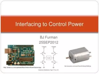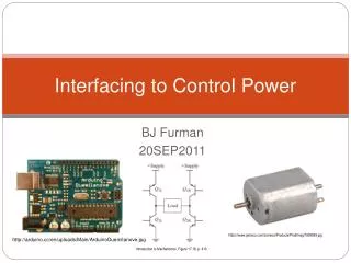
Introduction to Interfacing Projects
Introduction to Interfacing Projects. Nareen Khan. Using Turing. Command to send data to parallel port parallelput (x : int) The command sends 1 byte of data to the parallel port at a time. Using 1 byte (8 bits) we can represent 2 8 =256 different states.

Introduction to Interfacing Projects
E N D
Presentation Transcript
Introduction to Interfacing Projects Nareen Khan
Using Turing • Command to send data to parallel port parallelput (x : int) • The command sends 1 byte of data to the parallel port at a time. • Using 1 byte (8 bits) we can represent 28=256 different states. • The 8 bits are sent along the Data pins on the parallel port (Pins 2-9, D0-D7)
Data Lines (D) used for output. 13 12 11 10 9 8 7 6 5 4 3 2 1 25 24 23 22 21 20 19 18 17 16 15 14 Grounds D7 D6 D5 D4 D3 D2 D1 D0 Status Lines (S) used for input. Control Lines (C) may be used for input / output Understanding the Parallel Port
0 0 0 1 0 0 0 1 1 0 0 1 0 0 0 1 0 1 0 0 1 0 1 0 0 1 0 0 1 0 1 1 Binary on the Parallel Port • parallelput(0) • parallelput(1) • parallelput(37) • parallelput(255) The integer parameter is translated into binary and each bit corresponds to one of the data pins on the parallel port. Unsure of your conversions? Try this utility.
220Ω Pin 2 Voltage from parallel port Pin 18 What does the circuit look like? parallelput(0) Switch is open, no path, LED off parallelput(1) Switch is closed, path exists, LED on
Connected vertically in blocks of 5 Connected horizontally Breadboard Basics
1) –’ve lead is shorter Light Emitting Diodes • LED’s will only work if they are installed in the right direction. • Here are three ways to tell which is the negative (-’ve) lead.
2) Internal segment is larger Light Emitting Diodes • LED’s will only work if they are installed in the right direction. • Here are three ways to tell which is the negative (-’ve) lead.
3) Flat side on lip Light Emitting Diodes • LED’s will only work if they are installed in the right direction. • Here are three ways to tell which is the negative (-’ve) lead. TopView
Wiring an LED +’ve, Long Lead
Project Samples Traffic Intersection
The Traffic Intersection Project Steps: • Wire six LED / resistor pairs on breadboard • Attach the wires to your model • Write your program • Enjoy hours of staring at the lights change
Step 1 – Wiring the lights +’ve, Long Lead -’ve, Short Lead
Step 2 – The D-Sub Connector • Attach your wires to the crimp pins. • Be sure to press the clamps down tight on the wire. • Push the crimped pin into the D-Sub Connector (it’s a tight fit). • Repeat for the other 7 wires.
Test your interface • Once you’ve got the wires connected to the parallelport, you can test the interface. • Try : parallelput(255) This should turn on all your lights.
Making The Turing Program 1 • Make a Program Header % % The "trafficIntersection" program % Course Code: ICS 3M1 % Instructor: Your Teacher % Date: April 25, 2007 % Initial Release % % This Program simulates a traffic intersection in graphics. It can also properly drive the actual % intersection by use of a parallel port and binary outputs.
Making The Turing Program 2 • Create a User Defined Data Type type trafficState: % data type trafficState will store various components of traffic states. record timeWait : int % var for the time in that state binState : int % binary value of that state (more details see pin output state table NSPic : string % var for the state of the NS light EWPic : string % var for the state of the EW light end record
Making The Turing Program 3 • Create a User Defined Data Type drawfillbox(0, 0, maxx, maxy, 54) % code for background colour % The 6 states are declared as an array of trafficState data type var trafficPattern : array 1 .. 6 of trafficState % Below contains the value of each of the states % timeWait: Green light - 5 sec. % Yellow light - 2 sec. % Both red light - 1.25 sec. % binaryStates in decimal: NS green - 1 % NS yellow - 2 % NS red - 4 % EW green - 8 % EW yellow - 16 % EW red - 32
Making The Turing Program 4 • Note the binary States listed below drawfillbox(0, 0, maxx, maxy, 54) % code for background colour % The 6 states are declared as an array of trafficState data type var trafficPattern : array 1 .. 6 of trafficState % Below contains the value of each of the states % timeWait: Green light - 5 sec. % Yellow light - 2 sec. % Both red light - 1.25 sec. % binaryStates in decimal: NS green - 1 % NS yellow - 2 % NS red - 4 % EW green - 8 % EW yellow - 16 % EW red - 32
Making The Turing Program 5 • Then Define Each Traffic Pattern in this manner… %NS Green EW Red trafficPattern(1).timeWait := 5000 trafficPattern(1).binState := 1 + 32 trafficPattern(1).NSPic := "trafficgreen.bmp" trafficPattern(1).EWPic := "trafficred.bmp“ %NS Yellow EW Red trafficPattern(2).timeWait := 2000 trafficPattern(2).binState := 2 + 32 trafficPattern(2).NSPic := "trafficyellow.bmp" trafficPattern(2).EWPic := "trafficred.bmp“ etc…
Making The Turing Program 6 • Create a Procedure % procedure for loading the pictures in the different states procedure drawIntersection (NSFile : string, EWFile : string) Pic.ScreenLoad (NSFile, 250, 250, 0) Pic.ScreenLoad (EWFile, 100, 150, 2) Pic.ScreenLoad (NSFile, 250, 50, 0) Pic.ScreenLoad (EWFile, 400, 150, 2) end drawIntersection
Making The Turing Program 7 • Finally, cycle through the lights… % Loop to make the cycle continuous for i : 1 .. 4 % Loop for each of the traffic states and giving drawIntersection the images to change for j : 1 .. 6 drawIntersection (trafficPattern(j).NSPic , trafficPattern(j).EWPic) parallelput (trafficPattern(j).binState) % send info to parallel port delay (trafficPattern(j).timeWait) % delay the amount of milliseconds indicated in traffic state end for end for
Making The Turing Program 8 • Make Sure You Have These Graphics Files