Download
1 / 46
460 likes | 587 Views
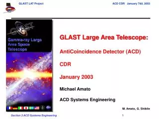
Gamma-ray Large Area Space Telescope. GLAST Large Area Telescope: AntiCoincidence Detector (ACD) CDR January 2003 Michael Amato ACD Systems Engineering M. Amato, G. Shiblie. Outline. System Overview Requirements and Systems Documentation Interfaces Design Decisions/Major Trades

E N D
Gamma-ray Large Area Space Telescope GLAST Large Area Telescope: AntiCoincidence Detector (ACD) CDR January 2003 Michael Amato ACD Systems Engineering M. Amato, G. Shiblie
Outline • System Overview • Requirements and Systems Documentation • Interfaces • Design Decisions/Major Trades • Verification • Risk • Technical Issues and Status
System Overview • TILE SHELL ASSEMBLY • 89 Plastic scintillator tiles • Waveshifting fiber light collection (with clear fiber light guides for long runs) • Two sets of fibers for each tile • Tiles overlap in one dimension • 8 scintillating fiber ribbons cover gaps in other dimension (not shown) • Supported on self-standing composite shell • Covered by thermal blanket + micrometeoroid shield (not shown) • BASE ELECTRONICS ASSEMBLY • 194 photomultiplier tube sensors (2/tile) • 12 electronics boards (two sets of 6), each handling up to 18 phototubes. Two HVBS per electronic chassis Prototype ACD tile read out with Wavelength Shifting Fiber Tile Shell Assembly (TSA) Base Electronics Assembly (BEA)
System Overview • Tile Detector Assembly (TDA) Scintillating Detector Tile Clear fiber PMT connectors Clear fiber connector Wave shifting fiber Flexures (4 per tile) Clear fiber connector
System Overview • Shell & Tile Shell Assembly (TSA) Composite Shell Flexures to Base Frame TDAs on Shell become the TSA
System Overview • Electronics Chassis PMT Housings PMT Rails Power distribution board BEA Connectors BEA Connectors PMT resistor networks Free boards (2) Chassis structure HVBSs (under FREE brds, 2 for each brd)
System Overview • Base Frame Assembly becomes Base Electronics Assembly with electronics chassis installed Assembled ACD Base Frame LAT Grid Electronics Chassis
Detector Tiles Detector Tiles Detector Tiles Detector Tiles System Overview
REQUIREMENTS ( & SYSTEMS DOCUMENTATION )
Level I Project Specifications SPECIFICATION DOCUMENT TREE Program Plan Requirements Level II System Specifications Level II(a) System Operations Concept Document GLAST00089 Science Req’ts Document GLAST00010 Mission Assurance Requirements GLAST00110 Mission System Specification GLAST00074 Level II(b) Element Spacecraft Performance Spec. LV Interface Specification SC-SI Interface Specification GLAST00038 GBM Instrument Performance Spec. LAT Instrument Performance Spec. LAT-SS-00010 SGL Comm Interface Spec. Inter-Center Interface Spec. GBM IOC Specification Science Support Center Spec. Mission Ops Center Spec. LAT IOC Performance Spec. LAT-SS-00015 Level III Subsystem Specifications LAT SAS Spec. LAT-SS-00020 LAT - ACD Spec. LAT-SS-00016 LAT - TKR Spec. LAT-SS-00017 LAT - CAL Spec. LAT-SS-00018 T&DF Spec. LAT-SS-00019 Aux. Subsystem Spec. LAT-SS-000xx LAT IOC Spec. LAT-SS-00021 LAT Interface Spec. LAT-SS-000xx Document under control of the LAT Project Document not under control of the LAT Project GLAST Requirements Flow
ACD Requirements Flow/Relationships Requirements Interface Control Approved (Under CM control) Verification LAT Level II (b) Specifications/Requirements LAT-SS-00010 In Sign Off LAT Verification Plan LAT-MD-00408 Mature Draft Draft ACD Inst Science Simulations ACD Performance Verification Plan ACD-PLAN-000050 LAT Continuous Risk Management Plan LAT-MD-00067 Incomplete-drafts ACD Level III Requirements LAT-SS-00016 ACD I&T Plan LAT-TD-00430-D1 LAT Environmental Spec LAT-TD-00788 LAT Contamination Cntrl Plan LAT-MD-00404 Combined ACD-LAT Electrical, Mechanical, Thermal ICD LAT-SS-00363 ACD Inst Science Simulations ACD Calibration Plan& ACD Comprehensive Performance Test Plan ACD Level IV Requirements ACD-RQMT-000029 ACD-LAT Interface Definition Drawings (IDD) * LAT-DS-00309 ACD, Subsystem and Component procedures and Test plans Outline Drawing ACD Electrical Specification ACD-SPEC-000061 Development and Eng model versions
ACD Requirements Database • ACD uses our Requirements Database in DOORS to Track Requirements ACD Level III Requirement Database (DOORS) Active Links between Requirements ACD-LAT ICD DOORS Database Active Links between Requirements Screen capture of level IV doors table ACD Level IV Requirement Database (DOORS)
Level III Key Requirements Summary Reference: LAT-SS-00016 • You have already seen in ACD Overview presentation on how the two requirements in red need to be traded off against each other and how we came to a good balance between the two.
Level IV Requirements Outline 5.2Charged Particle Detection 5.3Adjustable Threshold on VETO Detection of Charged Particles 5.4False VETO due to Electrical Noise 5.5High-Threshold Detection 5.6Adjustable High-Threshold 5.7Level 1 Trigger Acknowledge (TACK) 5.8Signals - (8 lower level requirements) 5.9ACD Performance Monitoring - (10 lower level requirements) 5.10High Voltage Bias Supply - (14 lower level requirements) 5.11PMT - (6 lower level requirements) 5.12Radiation Tolerance - (2 lower level requirements) 5.13Reliability - (6 lower level requirements) 5.14Commands - (10 lower level requirements) 5.15Output Data Formats 5.16Power Consumption 5.17Total ACD Mass 5.18Environmental Requirements - (11 lower level requirements) 5.19Performance Life 5.20Rate Requirement for Operation within Specification 5.21Testability 5.22Center of Mass 5.23Volume 5.24Instrument Coverage 5.25LAT to ACD Gap. 5.26Material interaction of gamma radiation (Gamma radiation due to ACD material interactions) 5.27Thermal Blanket/ Micrometeoroid Shield Areal Mass Density 5.28Gaps between scintillating tiles 5.29Light Throughput
ACD Requirements • Some important requirements flow through a science simulation ACD Simulation Input Parameters • Active elements input • Tile performance • PMT performance • Ribbon performance • Passive elements • Clear fiber performance • Wave shifting fiber performance • Fiber connectors performance • Dead area • Gap predictions • (between tiles • and at corners) ACD channel performance and 0.9997 overall efficiency ACD Science Instrument Simulation
BFA Design • BFA connection to LAT Grid • Connected in 4 corners, each with 3 fasteners and a shim. • Registration to LAT Grid is planned via a pin and slot common to both the BFA and the LAT Grid. BFA Corner Shim LAT Grid
BFA Design • BFA connection to LAT Grid • At each of 4 mid-span locations 2 fasteners and slip fit pin • Gap Between ACD and LAT Grid is taken up with adjustable snubbers. • Pin match drilled to LAT Grid after BFA is completed. • Pin is captured to accommodate slip fit. Mid Span Shell Flexure Pin Jam Nut Snubber Fastener Washers
Electrical Interface • 24 identical robust circular connectors (38999, series 2) & 2 circular housekeeping connectors (38999, series 2) • Parts, pin outs, signal def, grounding all defined in ICD • DATA PRODUCTS • (defined in Reqs. and • specified in ICD) • Channel specific charged • particle VETOs • VETO hit maps • Pulse Height Analysis (PHA) • Diagnostics • Housekeeping (thermistor • output, voltage monitor • output, direct to AEM)
ACD Technical Budget Summary Technical Resources – • ACD Mass • Allocation 280 kg (raised 15% from ΔPDR) • ACD detailed estimate 270 kg • ACD Power • Allocation 31 W (conditioned) • ACD detailed estimate 14 W max • Thermal Interface (max dissipation across ACD-LAT interface) • Dissipation Allocation 16 W • Dissipation Estimate <14 W
Design Decisions - R&D Testing • R&D Testing: Identify optimum design in terms of tile efficiency and light collection and map the response (light yield, efficiency) of a fiber/tile configuration in detail. • Determine testing methodology and construct test configuration -complete • Determine optimum fiber spacing in tile –complete (LAT-TD-00438) • Determine optimum groove depth –complete (LAT-TD-00438) • Determine edge effects –complete (LAT-TD-00438) • Determine tile uniformity – complete (LAT-TD-00438) • Determine effects of fiber end treatments (Al’ized ends) – complete (LAT-TD-00438) • Determine fiber length effects –complete (LAT-TD-00438) • Determine MIP light yield in p.e.’s, and PMT gain requirements –complete (LAT-TD-00438) • Determine effects of broken fibers – complete (LAT-TD-00438) • Production Testing: Develop and implement test procedure and fixture to verify performance of every tile. • Experience derived from R&D Testing will determine testing methodology and requirements • Tile Detector Assembly, Vibration, Thermal Vacuum and Performance tests completed (see ACD CM system) • Long tile and ribbon tests completed (LAT-TD-01239)
Design Decisions –Major Trades (since PDR) • BEA repackaging to facilitate trouble shooting, access, and efficient spare approach • Went from FREE boards being vertically mounted one behind the other to a structural element to horizontally mounted Free boards, both accessible from the front, mounted to a removable chassis. • Complete, tested (including thermal vac cycles) spare chassis can replace a troubled chassis. • Returned to two HVBS per FREE board (went to one in de-scope) • Overall efficiency trade study • Detector channel study resulted in • Rerouting fibers to improve efficiency of channels with longest fibers • Re-mapping of PMTs to facilitate above rerouting and to reduce fiber crossings in areas with little volume. • Increase in the thickness of the top center row of detectors (longest fiber run to PMTs) • No better performing clear fiber options found • Gap analysis study • Structural load and thermal motions were analyzed to determine minimum gaps • Vibration tests on some gap scenarios were run • Third fiber row was added to scintillator ribbons. • Some tile sizes modified to increase overlap • Analog ASIC design approach and testing scenario changed (modified the design and brought in additional outside expertise) • Micrometeoroid design change approach (additional spacer vs additional layers to accommodate reduced performance prediction from new analysis model) • Smaller changes – Added two instrumentation connectors, changed connector type to lower profile connector, lower tile design modifications
ProtoFlight Development Flow Development Unit Dev Unit Mods folded Design Fab Test into Engineering Units Phase Design NASA GSFC - GLAST ACD Requirements Review Engineering Unit Design Fab Test Phase Due to a project de-scope, the ACD does not have an ETU. Engineering units will be built for several critical subassemblies. Environmental Testing Peer Qualification Level Reviews Pre-Fab Review Eng Unit Mods folded into Flight Design Flight Unit Design Fab Test Phase Peer Reviews Flight Environmental Testing Manufacturing Acceptance Level Readiness Review
ACD Requirements (direct and derived) ACD Verification Plan ACD Requirements and Verification Tracking GLAST LAT Budgets GLAST LAT Science and Mission Requirements Allocation GLAST LAT Verification Plan Tracking Subsystem Level Tests and Procedures Subsystem Level Tests and Procedures Tracking Analysis & Inspection Analysis & Inspection NASA GSFC - GLAST ACD Testing Testing
ACD Verification Database • ACD has created a Verification database in DOORS linked to the • Requirements Database to Track Verification (Verification Plan - ACD-PLAN-000050) ACD Verification Tracking Database Links between Requirements ACD Level III and IV Requirements Database ACD-LAT ICD Requirements and Verification Database ACD Allocation Tables ACD Test Databases
Risk • If failures occur, ACD is designed to fail ‘gracefully’, major failures result in incremental steps in performance. Other than a major micrometeoroid hit, it takes multiple failures to fail a detector channel. Complete detector channel failures leave holes in coverage. • Micrometeoroid shield penetration is the only in orbit single point failure risk. ACD fails to meet the efficiency requirement with one tile destroyed by micrometeoroid penetration. The only other way to lose a entire detector channel is for multiple failures of other components. • A GARC failure results in loss of 18 PMTs leaving 18 detector tiles operating on one PMT, marginally meets efficiency requirement. • Each Detector tile has fibers leading to two separate PMTs on separate electronic chassis. PMTs are powered by separate HVBSs. • Each electronic chassis has redundant HVBSs. • PMTs can be adjusted in orbit to counteract degradation. • New micrometeoroid shield orbit debris predictions resulted in reduction in predicted performance. Design being modified to increase performance.
Risk • As part of the reliability/ risk program, the following additional activities have been performed in preparation for CDR: • Failure Modes and Effect Analysis and Critical Items List ACD-RPT-000042 (LAT-TD-00913) • Limited-Life Item Analysis (LAT-TD-00523) • Reliability Assessments and Worse Case Analysis (ACD-RPT-000071) • Fault Tree (ACD-RPT-000072) • Parts Stress and De-rating Analysis • Continuous Risk Management Plan (LAT-MD-000067) • Refer to Safety & Mission Assurancepresentation for key results.
RISK Redundancy TDA etc Electronics Shielding/blanket
Technical Issues and Status Technical Issues and Requirement Non-compliance * • Electronics Chassis Packaging – Progress continues to be made on finalizing BEA electro-mechanical packaging design. STATUS and RESOLUTION - Structure design/analysis is fairly complete, some tweaks due to analysis have just been completed. May relax some tight fits on harness to reduce assembly risk. Had to wait for side stay clear growth sign off to consider this. See issue below. • Potential BEA connector side stay clear violation (ICD/IDD, Level III, 5.22)– LAT Connectors could, depending on tolerance stack up, extend slightly into stay clear. STATUS and RESOLUTION - Changed to lower profile connector and pushed connector rear harness dimensions down. Design now fits into old stay clear with no margin. LAT pursued 1cm expansion of side stay clear with spacecraft vendor and project office. Agreed to by all parties and now reflected in version of IDD currently in sign off. This will allow for margin, relaxation of tight fits and potential expansion of harness size based on engineering model results. Stay clear issue is Fully Resolved. • Analog ASIC design * (see electrical presentation)- We have caught a variety of problems in the analog ASIC design. Some functions were not working. Design has been updated. STATUS and RESOLUTION –We have solved most of the problems and modified the design for latest fab runs. We have received additional SLAC expertise and asked for some GSFC expertise to help with final design updates and more importantly to help us test for future ones in a more reliable way. • 5 Year Reliability* (Level III 5.13, 5.14 & 5.4), Our overall 5 year reliability calculations show we are slightly below meeting our Level III efficiency requirement (.92 to .95 vs the .96 req). Other reqs are met at .96 reliability or better. STATUSand RESOLUTION We are revisiting provided numbers and internal margins. We are marginal only in meeting the efficiency req for 5 years, not other requirements. The reliability requirement flow down may have to be reviewed at the GLAST project level.
Technical Issues and Status Technical Issues and Requirement Non-compliance * The next two issues involve components that go into determining if we meet our overall efficiency requirements. Changes in these areas had to go through the ACD Instrument science simulation code to see their combined effect on the overall efficiency • Long Fibers/Efficiency Issue ( Level III, 5.4 ) – The length of some fibers were long, combined with fibers not quite performing as advertised, caused light yield at PMT to not meet requirement for some channels. STATUSand RESOLUTION –Re-mapped the detector to PMT locations, which allowed us to shorten our optical fiber lengths, has been forwarded to LAT which has agreed to change which is reflected in updated ICD currently in signature cycle. Mechanical optimization also complete. Primarily we re-routed the fibers from the outside top and second row tiles on the X side around the corner to FREE cards on the Y side, This change alone has brought our problem side detectors into compliance with individual channel efficiency requirements they needed to meet our overall efficiency requirement. We have also increased the thickness of the top center row tiles to 1.2 cm to improve their performance. Fully resolved. • Tile Gap/Efficiency Issue* (Level III, 5.4) – The gaps that are needed between tiles reduce the ACD efficiency. The size of gaps are driven by thermal expansion/contraction, tile vibration, and tolerances. STATUSand RESOLUTION -Several solutions particular to certain gaps have been decided on. Acoustic analysis and TDA test results have provided updated minimum gaps which are run through the simulations to update efficiency. The smaller gaps provided in the update make in unlikely additional steps will be needed (for example a reduction on the survival test high temp spec). Will be resolved when simulation results ( expected this week) show ACD meets eff. req. with new gaps (which we expect them to show) and those gaps are fully represented in CAD design
Technical Issues and Status Technical Issues and Requirement Non-compliance * • Micrometeoroid shield, (Level IV Req 5.13.5, 5.18.11) – Reduced performance prediction from new analysis model. Related issue, LAT has recently informed us updates to the environment for debris, Micro-meteoroid and Atomic Oxygen has not yet been ‘officially’ defined for the LAT by the project office. STATUSand RESOLUTION - Redesign is in progress which will solve this. (we will have to track the updates in official req flow down before actual implementation) • Light leaks in TDA and PMT assembly* (Level III, 5.3, 5.2) – Light leak test revealed small light leaks in a bread board TDA. STATUSand RESOLUTION - Fixes to leaks at PMT have been proposed and agreed to. Minor changes in sealing and taping at connector interfaces and tile will be tested for effectiveness. TDA Handling procedure is being created to prevent small punctures. • Other issues –Development unit PMT failure , we had a development PMT fail after assembly. Evidence points to vac leak. Failure Review Board is currently has created and has implemented a plan to determine exact failure cause. IDD clarifications – IDD still had some tolerance and dimensioning approach clarifications which were very recently worked out. Some ‘growing pains’ for being first LAT subsystem through CDR/Peer Review (i.e. updating some interface documentation ). Tile mount design mechanical peer review input – Lower tile mount slip stick design and angle mount of flexures not yet verified by test. • Other recently resolved Non compliance Issues – Mass (Level III, 5.19) allocation increased from delta PDR level, Attenuation(Level IV 5.26) calculation updated shows we marginally meet 6% requirement
SUMMARY • Accounting and tracking of requirements is well defined. • Requirements flow and relationships are well defined. • We have showed our major system interfaces. • Systems and interface documentation is signed off in the CM system or has entered that final process. • We have discussed our development test work and major trade studies since PDR. • Our verification approach and tracking is clearly delineated and documented. • Major risks and risk mitigations are understood. • A limited number of technical issues must be resolved before the manufacturing readiness reviews in those areas. • Approaches to addressing those issues are identified.
Current Issues and Status Partial detector Gaps table from last month for reference