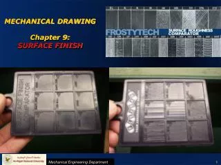
MECHANICAL DRAWING Chapter 9: SURFACE FINISH
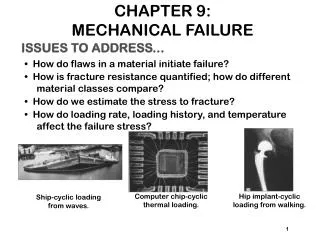
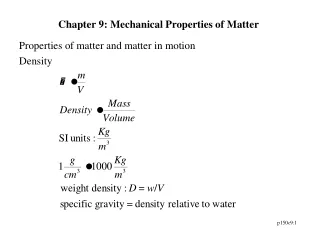
MECHANICAL DRAWING Chapter 9: SURFACE FINISH . INTRODUCTION. The modern demands of the automobile, the airplane, and other modern machines (heavier loads, higher speeds with less friction) need for accurate control of surface.

MECHANICAL DRAWING Chapter 9: SURFACE FINISH
E N D
Presentation Transcript
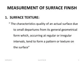
INTRODUCTION • The modern demands of the automobile, the airplane, and other modern machines (heavier loads, higher speeds with less friction) need for accurate control of surface. • Not all surfaces can be finished because of cost constrains. Few surfaces requires special surface finish and should indicate on drawing by using surface finish symbol. • The ideal surface finish is the roughest that will do the job satisfactorily. • ANSI/ASME recommended a system of surface texture symbols.
Objectives of Machining Symbols (Finish Marks) • Define the surface to be machines or finished. For die-maker a finish mark means that allowance of extra metal in the rough workpiece must be provided for the machining. • Specify a particular surface finish • Determine the manufacturing process Old finish marks symbol
SURFACE ROUGHNESS Surface roughness symbols: Surface texture symbols are used to define surface texture, roughness and lay. Surface may be produced by any method Material removal allowance. 3.5 is the amount of stock to be removed 3.5 Material removal by machining is required to produce the surface More surface characteristics are specified in these spaces. Material removal prohibited
00 00 00 SURFACE ROUGHNESS Application of surface roughness symbol on drawing: • Normal to the surface. • The point of the symbol should be directed inward toward the body metal, not upside down. • Could be vertical or horizontal as the surface, but not at any angle. • Could be provided as a general note. Symbol Approx. 3X 3X Letter height = X 1.5X 60°
Roughness Roughness Roughness SURFACE ROUGHNESS Definitions: • Surface texture: includes roughness, waviness, lay and flaws. • Profile: is the contour (shape) of a surface in a plane perpendicular to the surface. • Micrometer [μ] : 1*10-6 m = 1/1000000 m • Roughness: small peaks and valleys found in the surface (fine irregularities) • Roughness height: arithmetical average deviation [μ].
Roughness Roughness Roughness SURFACE ROUGHNESS Definitions: • Roughness width: distance between two peaks that make the roughness • Waviness: larger deviation from the nominal surface on which the roughness is superimposed • Waviness height: distance from peak to valley • Waviness width: distance between successive wave peaks or successive wave valleys. • Lay: directions of tool marks, or grains of surface • Flaw: surface defects.
Roughness SURFACE ROUGHNESS Location of surface specifications on surface finish symbol: • Maximum values are specified
SURFACE ROUGHNESS Lay symbols: If it is necessary to specify the direction of the tool marks, it must be applied to the surface texture symbol:
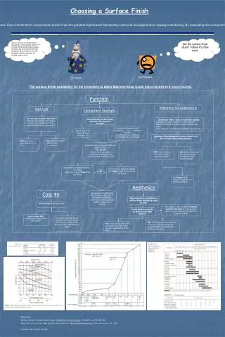
SURFACE SPECIFICATIONS Surface finish symbol (machining symbol) can be used to specify the surface finish and machining/manufacturing process. • Surface finish: -is usually specified as a roughness value in micrometers printed above the finish symbol. -The roughness value is related to the machining process. See Table. -For more exact machining the upper and lower limits of roughness are specified. • Specifying process: Could be directly specified on the finish symbol.
EXAMPLES: Application of surface texture values to symbol
ADDITIONAL INFORMATION • Usually all information are not required. Only roughness height and machine allowance is important. In this case basic symbol is used. • Roughness height in [μm] or in [μ inch]. All other in mm or inch.