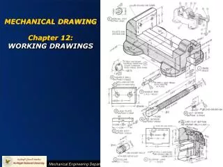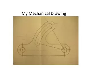
MECHANICAL DRAWING
MECHANICAL DRAWING. Why do we draw?. To communicate!!!. Why does it matter?. What’s the use of a great idea if you cant convey it to any one else. No one is an expert at everything, so we must collaborate to reach a common goal. Communication with Drawing (things to consider).

MECHANICAL DRAWING
E N D
Presentation Transcript
Why do we draw? To communicate!!!
Why does it matter? What’s the use of a great idea if you cant convey it to any one else. No one is an expert at everything, so we must collaborate to reach a common goal.
Communication with Drawing(things to consider) Subject – what you are trying to convey (Process, structure, function, material, etc….) Audience – who you are communicating with (designer, client, manager, public, other engineers)
Types of Mechanical Drawing Drawing types we will explore today • Sketches • Isometric Drawings • Orthographic Projections
When is a sketch useful? Think about • What (subject) • Who (audience)
– look and feel Sketching
– to show process Sketching
– to explore form Sketching
When is a technical drawing useful? Think about • What (subject) • Who (audience)
Isometric Drawing • front corner is centered and vertical • bottom edges slant up at a 30 degree angle from horizontal (You should be viewing 3 of the 6 faces of a cube) 30° 30°
ISOMETRIC DRAWING • height (“vertical”) lines are always drawn vertically in at their true (or scaled) length • width and depth (“horizontal”) lines are drawn 30 degrees from the horizontal at their true (or scaled) length • all lines parallel to the height, width or depth are at their true (or scaled) length • lines not parallel to these axes are not drawn at their true length height width depth
Isometric Drawing - Dimensions Identify line to dimension
Isometric Drawing - Dimensions Draw extension lines
Isometric Drawing - Dimensions Draw dimension lines
Isometric Drawing - Dimensions draw as many dimensions as you would need to make the part (no more no less)
did anyone have an object that couldn’t be fully expressed with a single isometric drawing?
ORTHOGRAPHIC PROJECTION Orthographic Projection Isometric Drawing
ORTHOGRAPHIC DRAWING – PLANNING • what is the minimum number of views required to capture every object feature? often the answer is three, but it could be less or more! • what is the best way to lay out these drawings • best use of paper, should drawings be scaled up or down? • we will be dimensioning drawings, so leave enough space around each view to add dimensions • think about the order of inking to avoid smudging
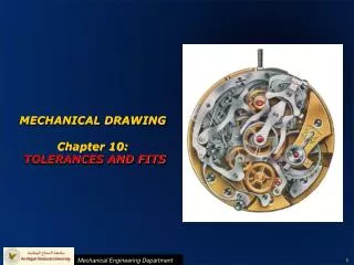
ORTHOGRAPHIC DRAWING – LINEWEIGHTS AND STYLES • thick continuous line – used for visible edges and outlines • thin continuous line – hatching, short center lines, dimensions or projection lines • thin dash-dot line – center lines, to identify the center of a circle or a line of symmetry • thin dashed line – used for important hidden detail, such a hole in a solid or a wall thickness
How do I bring this to the classroom?????? • Use sketching for general design, planning and idea sharing • Look and feel • Form • process • Use technical drawing for final details such as assembly or part drawings for fabrication • Isometric • Orthographic • Assembly