CHAPTER 9: MECHANICAL FAILURE
CHAPTER 9: MECHANICAL FAILURE. ISSUES TO ADDRESS. • How do flaws in a material initiate failure?. • How is fracture resistance quantified; how do different material classes compare?. • How do we estimate the stress to fracture?.

CHAPTER 9: MECHANICAL FAILURE
E N D
Presentation Transcript
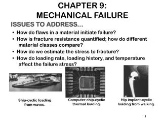
CHAPTER 9:MECHANICAL FAILURE ISSUES TO ADDRESS... • How do flaws in a material initiate failure? • How is fracture resistance quantified; how do different material classes compare? • How do we estimate the stress to fracture? • How do loading rate, loading history, and temperature affect the failure stress? Computer chip-cyclic thermal loading. Hip implant-cyclic loading from walking. Ship-cyclic loading from waves. 1
EX: FAILURE OF A PIPE • Ductile failure: --one piece --large deformation • Brittle failure: --many pieces --small deformation 3
MODERATELY DUCTILE FAILURE • Evolution to failure: 50 mm 50 mm • Resulting fracture surfaces (steel) 100 mm particles serve as void nucleation sites. 4
BRITTLE FRACTURE SURFACES • Intragranular (within grains) • Intergranular (between grains) 304 S. Steel (metal) 316 S. Steel (metal) 160mm 4 mm Polypropylene (polymer) Al Oxide (ceramic) 3mm 1 mm 5
IDEAL VS REAL MATERIALS TS << TS engineering materials perfect materials • Stress-strain behavior (Room T): • DaVinci (500 yrs ago!) observed... --the longer the wire, the smaller the load to fail it. • Reasons: --flaws cause premature failure. --Larger samples are more flawed! 6
FLAWS ARE STRESS CONCENTRATORS! • Elliptical hole in a plate: • Stress distrib. in front of a hole: • Stress conc. factor: • Large Kt promotes failure: 7
ENGINEERING FRACTURE DESIGN • Avoid sharp corners! 8
WHEN DOES A CRACK PROPAGATE? • rt at a crack tip is very small! • Result: crack tip stress is very large. • Crack propagates when: the tip stress is large enough to make: K ≥ Kc 9
GEOMETRY, LOAD, & MATERIAL • Condition for crack propagation: K ≥ Kc Stress Intensity Factor: --Depends on load & geometry. Fracture Toughness: --Depends on the material, temperature, environment, & rate of loading. • Values of K for some standard loads & geometries: 10
FRACTURE TOUGHNESS increasing Based on data in Table B5, Callister 6e. Composite reinforcement geometry is: f = fibers; sf = short fibers; w = whiskers; p = particles. Addition data as noted (vol. fraction of reinforcement): 1. (55vol%) ASM Handbook, Vol. 21, ASM Int., Materials Park, OH (2001) p. 606. 2. (55 vol%) Courtesy J. Cornie, MMC, Inc., Waltham, MA. 3. (30 vol%) P.F. Becher et al., Fracture Mechanics of Ceramics, Vol. 7, Plenum Press (1986). pp. 61-73. 4. Courtesy CoorsTek, Golden, CO. 5. (30 vol%) S.T. Buljan et al., "Development of Ceramic Matrix Composites for Application in Technology for Advanced Engines Program", ORNL/Sub/85-22011/2, ORNL, 1992. 6. (20vol%) F.D. Gace et al., Ceram. Eng. Sci. Proc., Vol. 7 (1986) pp. 978-82. 11
DESIGN AGAINST CRACK GROWTH K ≥ Kc • Crack growth condition: • Largest, most stressed cracks grow first! --Result 2: Design stress dictates max. flaw size. --Result 1: Max flaw size dictates design stress. 12
DESIGN EX: AIRCRAFT WING • Material has Kc = 26 MPa-m0.5 • Two designs to consider... Design B --use same material --largest flaw is 4 mm --failure stress = ? Design A --largest flaw is 9 mm --failure stress = 112 MPa • Use... • Key point: Y and Kc are the same in both designs. --Result: 112 MPa 9 mm 4 mm Answer: • Reducing flaw size pays off! 13
LOADING RATE • Increased loading rate... --increases sy and TS --decreases %EL • Why? An increased rate gives less time for disl. to move past obstacles. • Impact loading: --severe testing case --more brittle --smaller toughness 14
TEMPERATURE • Increasing temperature... --increases %EL and Kc • Ductile-to-brittle transition temperature (DBTT)... 15
DESIGN STRATEGY:STAY ABOVE THE DBTT! • Pre-WWII: The Titanic • WWII: Liberty ships • Problem: Used a type of steel with a DBTT ~ Room temp. 16
SUMMARY • Engineering materials don't reach theoretical strength. • Flaws produce stress concentrations that cause premature failure. • Sharp corners produce large stress concentrations and premature failure. • Failure type depends on T and stress: -for noncyclic s and T < 0.4Tm, failure stress decreases with: increased maximum flaw size, decreased T, increased rate of loading. -for cyclic s: cycles to fail decreases as Ds increases. -for higher T (T > 0.4Tm): time to fail decreases as s or T increases. 26