Download
1 / 20
200 likes | 457 Views
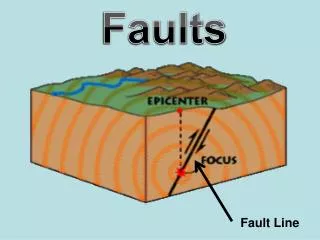
Resistance to Internal Faults. Martin Schaak Olaf Bischur Thomas Stommel. Topics. Resistance to internal faults Causes and physical effects Basic standard IEC 62271-200 Test object NXPLUS C Live test Analysis and review Open questions. Causes of Internal Faults.

E N D
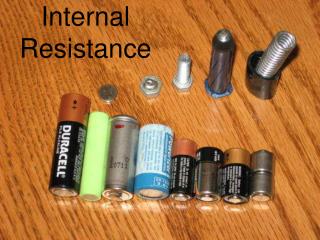
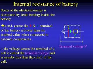
Resistance to Internal Faults Martin SchaakOlaf BischurThomas Stommel
Topics Resistance to internal faults • Causes and physical effects • Basic standard IEC 62271-200 • Test object NXPLUS C • Live test • Analysis and review • Open questions
Causes of Internal Faults • Ageing of insulating materials under electrical stress • Corrosion • Overstressing • Ferroresonance, overvoltages • Defective installation, incorrect maintenance • Maloperation • Pollution, humidity, small animals penetrating in the switchgear
Electrical Accidents • Reported electrical accidents in the sphere of activity of BGFE • 1 internal arcing fault per 10,000 GIS panels and year • 80 % • Electrical effects of high voltage • 67.5 % • Institute for the research of electrical accidents • 60 % • 1996-2000 • 49.3% • 47.1% • 2001-2005 • 40 % • 27.4% • 27.0% • 20.8% • 20 % • 5.8% • 1.5% • 0 % • Electric shock • Arcing fault • Electric shock and arcing fault • Arcing fault with electro-ophthalmia and • burns
Physical Effects of an Internal Fault Energy balance Radiation Temperature riseand pressure rise Electric arc,plasma beam with a temperature of about 20,000 °C Thermal conduction, melting Evaporation
Possible Effects of an Internal Fault • Light effect (blinding, shock) • Noise development (hearing damage) • Thermal load (heat, burns) • Smoke development (breathing) • Projection of parts (cuts) • Toxic effects (intoxication) • Pressure development (damage to buildings / walls and door), physiological influence on a person (shock, falling caused by defensive reaction, circulatory insufficiency)
Avoidance of Internal Faults • Quality during design, production and installation • Training of personnel (avoidance of maloperation) • Maintenance (replacement of worn-out parts, cleaning) • Active systems for fault detection Other measures for avoidance of internal arcs are described in IEC 62271-200, Table 2: “Locations, causes and examples of measures to reduce the probability of internal faults”
Comparison of the Internal Arcing Test IEC 60298 vs. IEC 62271-200
Designation of the Internal Arc Classification Classification: IAC ( “InternalArcClassified” ) Accessibility: A (F, L, R)* B (F, L, R)* C Test values: Current [ kA ] and duration [ s ] • * F = Front; L = Lateral; R = Rear Example 1: IAC A FLR 25 kA 1 sExample 2: IAC B FL 25 kA 1 s
Test Procedure For switchgears with internal arc classification (IAC) according to IEC 62271‑200: • Test object consists of 2 panels as a minimum • Test in every compartment and at least in the end panel • Completely equipped test specimen (reproductions are accepted) • Test only on not pre-stressed functional compartments • Defined distances (walls, ceiling) • 40 % to 50 % of the surface must be covered with indicators • Defined direction of power flow and points of arc initiation • SF6-insulation may be replaced by air • Evaluation of all five criteria Busbar compartment Circuit-breaker compartment Cable compartment
600 mm 800 mm 100 mm Test Arrangement Conditions (1) (a) Height of ceiling - Height of test object + 600 mm ± 100 mm - If height of test object ≤ 1.5 m > Min. height of ceiling 2 m (b) Rear wall - Non-accessible 100 mm ± 30 mm - Accessible 800 mm + 100 mm (c) Indicators - Covering 40 to 50 % (checker pattern)
Test Arrangement Conditions (2) For the test object in the room mock-up For the indicators
Acceptance criteria new new
Test Setup Current test object, open vessel and ignition wire
Test Parameters • Type of accessibility “A” • Free-standing arrangement • Short-circuit current: 25 kA • Short-circuit duration: 1 s • Height of ceiling: 2.8 m • Switch position of all devices: “CLOSED” • Operating tool inserted • Infeed via right-hand disconnector panel • 3-phase arc initiation in gas vessel of CB-panel at cable connection bushings • Direction of power flow as feeder panel IAC A FLR 25 kA 1 s
Test Preparations Arrangement of test object in room mock-up
Live Test Performance of internal arcing test (Changeover to high-power testing laboratory)
Switchgear front Camera A Switchgear side Camera B Camera C Flashback (Slow Motion of Live Test) Test recorded from different camera positions
Resulting Document As an example from previous tests