Download
1 / 85
880 likes | 1.31k Views
Chapter 4 Single Stage IC Amplifiers. Outline. Introduction Biasing mechanism for ICs High frequency response The CS and CE amplifier with active loads High frequency response of the CS and CE amplifier The CG and CB amplifier with active loads The Cascode amplifier

E N D
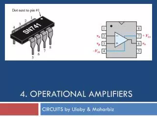
Chapter 4 Single Stage IC Amplifiers SJTU Zhou Lingling
Outline • Introduction • Biasing mechanism for ICs • High frequency response • The CS and CE amplifier with active loads • High frequency response of the CS and CE amplifier • The CG and CB amplifier with active loads • The Cascode amplifier • The CS and CE amplifier with source(emitter)degeneration SJTU Zhou Lingling
Introduction • Design philosophy of integrated circuits • Comparison of the MOSFET and the BJT (Self-Study) SJTU Zhou Lingling
Design Philosophy of Integrated Circuits • Strive to realize as many of the functions required as possible using MOS transistors only. • Large even moderate value resistors are to be avoided • Constant-current sources are readily available. • Coupling and bypass capacitors are not available to be used, except for external use. SJTU Zhou Lingling
Design Philosophy of Integrated Circuits • Low-voltage operation can help to reduce power dissipation but poses a host of challenges to the circuit design. • Bipolar integrated circuits still offer many exciting opportunities to the analog design engineer. SJTU Zhou Lingling
Biasing mechanism for ICs • MOSFET Circuits • The basic MOSFET current source • MOS current-steering circuits • BJT Circuits • The basic BJT current source • Current-steering SJTU Zhou Lingling
Biasing mechanism for ICs(cont’d) • Current-mirror circuits with improved performance • Cascode MOS mirrors • A bipolar mirror with base-current compensation • The wilson current mirror • The wilson MOS mirror • The widlar current source SJTU Zhou Lingling
The Basic MOSFET Current Source SJTU Zhou Lingling
The Basic MOSFET Current Mirror SJTU Zhou Lingling
Output Characteristic SJTU Zhou Lingling
MOS Current-Steering Circuits SJTU Zhou Lingling
The Basic BJT Current Mirror SJTU Zhou Lingling
A Simple BJT Current Source. SJTU Zhou Lingling
Current Steering SJTU Zhou Lingling
Current-Mirror Circuits with Improved Performance Two performance parameters need to be improved: • The accuracy of the current transfer ratio of the mirror. • The output resistance of the current source. SJTU Zhou Lingling
Cascode MOS Current Mirror SJTU Zhou Lingling
Current Mirror with Base-Current Compensation SJTU Zhou Lingling
The Wilson Bipolar Current Mirror SJTU Zhou Lingling
The Wilson MOS Current Mirror SJTU Zhou Lingling
The Widlar Current Source SJTU Zhou Lingling
High Frequency Response • The high-frequency gain function • Determining the 3-dB frequency • By definition • Dominant-pole • Open-circuit time constants SJTU Zhou Lingling
The High-Frequency Gain Function • Directly coupled • Low pass filter • gain does not fall off at low frequencies • Midband gain AM extends down to zero frequency SJTU Zhou Lingling
The High-Frequency Gain Function • Gain function • ωP1 , ωP2 , ….ωPn are positive numbers representing the frequencies of the n real poles. • ωZ1 , ωZ2 , ….ωZn are positive, negative, or infinite numbers representing the frequencies of the n real transmission zeros. SJTU Zhou Lingling
Determining the 3-dB Frequency • Definition or • Assume ωP1< ωP2 < ….<ωPn and ωZ1 < ωZ2 < ….<ωZn SJTU Zhou Lingling
Determining the 3-dB Frequency • Dominant pole If the lowest-frequency pole is at least two octaves (a factor of 4) away from the nearest pole or zero, it is called dominant pole. Thus the 3-dB frequency is determined by the dominant pole. • Single pole system, SJTU Zhou Lingling
Determining the 3-dB Frequency • Open-circuit time constants • To obtain the contribution of capacitance Ci • Reduce all other capacitances to zero • Reduce the input signal source to zero • Determine the resistance Rio seen by Ci • This process is repeated for all other capacitance in the circuit. SJTU Zhou Lingling
Example for Time Constant Analysis • High-frequency equivalent circuit of a MOSFET amplifier. • The configuration is common-source. SJTU Zhou Lingling
Example for Time Constant Analysis Circuit for determining the resistance seen by Cgs and Cgd SJTU Zhou Lingling
The CS Amplifier with Active Load • Current source acts as an active load. • Source lead is signal grounded. • Active load replaces the passive load. SJTU Zhou Lingling
The CS Amplifier with Active Load • Small-signal analysis of the amplifier performed both directly on the circuit diagram and using the small-signal model explicitly. • The intrinsic gain SJTU Zhou Lingling
The CS Amplifier with Active Load SJTU Zhou Lingling
The CE Amplifier with Active Load • Active-loaded common-emitter amplifier. • Small-signal analysis of the amplifier performed both directly on the circuit and using the hybrid-p model explicitly. SJTU Zhou Lingling
The CE Amplifier with Active Load • Performance of the amplifier • Intrinsic gain • Voltage gain SJTU Zhou Lingling
High-Frequency Response of the CS and CE Amplifier • Miller’s theorem. • Analysis of the high frequency response. • Using Miller’s theorem. • Using open-circuit time constants. SJTU Zhou Lingling
Miller’s Theorem Impedance Z can be replaced by two impedances: Z1 connected between node 1 and ground Z2 connected between node 2 and ground SJTU Zhou Lingling
High-Frequency Equivalent-Circuit Model of the CS Amplifier SJTU Zhou Lingling
Analysis Using Miller’s Theorem • Approximate equivalent circuit obtained by applying Miller’s theorem. • This model works reasonably well when Rsig is large. • The high-frequency response is dominated by the pole formed by Rsig and Cin. SJTU Zhou Lingling
Analysis Using Miller’s Theorem • Using miller’s theorem the bridge capacitance Cgd can be replaced by two capacitances which connected between node G and ground, node D and ground. • The amplifier with one zero and two poles now is changed to only one pole system. • The upper 3dB frequency is only determined by this pole. SJTU Zhou Lingling
Analysis Using Open-Circuit Time Constants SJTU Zhou Lingling
Analysis Using Open-Circuit Time Constants SJTU Zhou Lingling
The Situation When Rsig Is Low High-frequency equivalent circuit of a CS amplifier fed with a signal source having a very low (effectively zero) resistance. SJTU Zhou Lingling
The Situation When Rsig Is Low Bode plot for the gain of the circuit in (a). SJTU Zhou Lingling
The Situation When Rsig Is Low • The high frequency gain will no longer be limited by the interaction of the source resistance and the input capacitance. • The high frequency limitation happens at the amplifier output. • To improve the 3-dB frequency, we shall reduce the equivalent resistance seen through G(B) and D(C) terminals. SJTU Zhou Lingling
High-Frequency Equivalent Circuit of the CE Amplifier SJTU Zhou Lingling
Equivalent Circuit with Thévenin Theorem Employed SJTU Zhou Lingling
Two Methods to Determine the 3-dB Frequency • Using Miller’s theorem • Using open-circuit time constants SJTU Zhou Lingling
Active-Loaded CG Amplifier The body effect in the common-gate circuit can be fully accounted for by simply replacing gm of the MOSFET by (gm+gmb) SJTU Zhou Lingling
Active-Loaded CG Amplifier • Small-signal analysis performed directly on the circuit diagram with the T model of (b) used implicitly. • The circuit is not unilateral. SJTU Zhou Lingling
Active-Loaded CG Amplifier Circuit to determine the output resistance. SJTU Zhou Lingling
Performance of the Active Loaded CG Amplifier • Input resistance • Open-circuit voltage gain • Output resistance SJTU Zhou Lingling