
ELEC 412 RF & Microwave Engineering
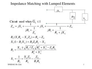
ELEC 412 RF & Microwave Engineering. Fall 2004 Lecture 19. Stub Tuner Matched RF Amplifiers. Stub tuners can be used to match sources and load to S 11 * and S 22 * of the RF BJT or FET Either open or short circuit stubs may be used

ELEC 412 RF & Microwave Engineering
E N D
Presentation Transcript
ELEC 412 RF & Microwave Engineering Fall 2004 Lecture 19 ELEC 412 - Lecture 19
Stub Tuner Matched RF Amplifiers • Stub tuners can be used to match sources and load to S11* and S22* of the RF BJT or FET • Either open or short circuit stubs may be used • When using short circuit stubs, place a capacitor between the stub and ground to produce RF path to ground – Do not short directly to ground as this will affect transistor DC biasing • High resistance /4 transformers or RFC’s may be used to provide DC path to transistor for biasing without affecting the RF signal path ELEC 412 - Lecture 19
Stub Tuner Matched RF Amplifier Series Resonant Ckt at Operating Frequency: Short Ckt at Resonance, Open Circuit at DC Stub tuners of two types: Base-Side: Open Circuit Stub w/ Isolation from DC Bias Circuit Using RFC. Collector-Side: RF Short Circuit Stub via By-Pass Capacitor l/4 Transformer: Transforms Short Circuit at Resonance to Open circuit at BJT Collector Thus Isolating RC from RF Signal Path Power Supplies Are Cap By-Passed and RF Input and Output are Cap Coupled The BJT “Self-Bias” Configuration Is Shown Which Produces Excellent Quiescent Point Stability ELEC 412 - Lecture 19
Stub Tuner Matched RF Amplifier Simpler method of bias isolation at BJT collector: CBP is RF short-circuit which when transformed by the Quarter-Wave Transformer is open circuit at the Single Stub Tuner and provides DC path for the Bias Network ELEC 412 - Lecture 19
Design Strategy: RF Amplifiers • Objective: Design a complete class A, single-stage RF amplifier operated at 1 GHz which includes biasing, matching networks, and RF/DC isolation. ELEC 412 - Lecture 19
Design Strategy: RF Amplifier • Design DC biasing conditions • Select S-parameters for operating frequency • Build input and output matching networks for desired frequency response • Include RF/DC isolation • simulate amplifier performance on the computer ELEC 412 - Lecture 19
Design Strategy: Approach For power considerations, matching networks are assumed lossless ELEC 412 - Lecture 19
Power Relationships Transducer Power Gain ELEC 412 - Lecture 19
Stability of Active Device ELEC 412 - Lecture 19
Stability of Amplifiers • In a two-port network, oscillations are possible if the magnitude of either the input or output reflection coefficient is greater than unity, which is equivalent to presenting a negative resistance at the port. This instability is characterized by |Gin| > 1 or |Gout| > 1 which for a unilateral device implies |S11| > 1 or |S22| > 1. ELEC 412 - Lecture 19
Stability Requirements • Thus the requirements for stability are and • These are defined by circles, called stability circles, that delimit |Gin| = 1 and | GL| = 1 on the Smith chart. ELEC 412 - Lecture 19
Stability Regions: Stability Circles • Regions of amplifier stability can be depicted using stability circles using the following: Output stability circle: Input stability circle: ELEC 412 - Lecture 19
Stability Regions: Stability Circles Where: ELEC 412 - Lecture 19
Stability Regions: Output Stability Circles ELEC 412 - Lecture 19
Stability Regions: Input Stability Circles ELEC 412 - Lecture 19
Different Input Stability Regions Dependent on ratio between rs and |Cin| ELEC 412 - Lecture 19
Unconditional Stability Stability circles reside completely outside |GS| =1 and |GL| =1. Rollet Factor: ELEC 412 - Lecture 19
Constant Gain Amplifier ELEC 412 - Lecture 19
Constant Gain Circles in the Smith Chart To obtain desired amplifier gain performance ELEC 412 - Lecture 19
Circle Equation and Graphical Display ELEC 412 - Lecture 19
Gain Circles • Max gain Gimax =1/(1-|Sii|2) when Gi = Sii* ; gain circle center is at dgi= Sii* and radius rgi=0 • Constant gain circles have centers on a line connecting origin to Sii* • For special case Gi = 0, gi= 1-|Sii|2 and dgi = rgi= |Sii|/(1+|Sii|2) implying Gi = 1 (0 dB) circle always passes through origin of Gi plane ELEC 412 - Lecture 19
Trade-off Between Gain and Noise ELEC 412 - Lecture 19


![G7 - PRACTICAL CIRCUITS [3 exam question - 3 groups]](https://cdn3.slideserve.com/7106848/g7-practical-circuits-3-exam-question-3-groups-dt.jpg)