Download
1 / 27
270 likes | 392 Views
Explore the ANSYS and SPARK analyses of the TF flag joint design, including thermal/electrical responses, inductive effects, force distribution, and more. Learn about contact resistance, temperature distributions, and peak temperature considerations.

E N D
NSTX TF Flag Joint Design Review April 10, 2003 Art Brooks
Overview of TF Flag Analyses • Thermal/Electrical Response ( ANSYS ) • Impact of Assumed Contact Resistance on Joint temperature and pulse length • Inductive Effects ( SPARK ) • Force Distribution ( SPARK )
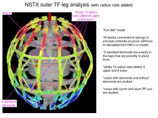
ProE Model of TF Flag Geometry Contact region Epoxy layer (not present in latest design) Inner Leg Outer Turn
Geometry Imported to ANSYS and Meshed Higher order tetra elements used to auto-mesh irregular geometry 71/2 KA Current
Contact Region Modeled as finite thickness with equivalent resistivity
71 KA Waveform Driving Thermal Model Analysis assumes the Full I2t (6.5e9 a2s) based on .7 sec FT and L/R decay.
End Of Flat-Top Temperature Distribution assuming 6 mW-in2 Note: 6 mW-in2 Contact Resistance requires ~1.4 ksi contact pressure (Copper-on-Copper)
End Of Flat-Top Temperature Distribution
Temperature Peaks shortly after EOFT 176 C Flat top would have to be shortened to ~0.26 s to limit max temperature to 120 C at 6 mW-in2
End Of Flat-Top Temperature Distributionassuming 4 mW-in2 Note: 4 micro-ohm-in2 Contact Resistance requires ~2.0 ksi contact pressure (Copper-on-Copper)
End Of Pulse Temperature Distribution
Again, Temperature Peaks shortly after EOFT Flat top would have to be shortened to ~0.41 s to limit max temperature to 120 C at 4 mW-in2
End Of Flat-Top Temperature Distributionassuming 1 mW-in2 Note: 1 mW-in2 Contact Resistance expected with Silver Plated Joint and minimum 1 ksi press
Temperature Peaks shortly after EOFT Flat top of 0.7 s achievable Max temperature less than 120 C at 1 mW-in2
Thermal Response Summary • Peak Temperature at Joint occurs near threaded inserts, but localized • Peak Temperature very dependent on Assumed contact resistance • Higher than expected contact resistance will force shortening of flat top at 6 kG • Full I2t achievable at 1 mW-in2 • Bulk Heating of Flag small. • Bulk Temperature not significantly impacted by assumption of contact resistance
Inductive Effects • ANSYS analyses of Joint Heating assumed currents were resistively distributed • SPARK Model used to assess current penetration • Time constants for current penetration shown to be small
SPARK Model of NSTX TF Coil With Current Flow Geometry Only
Current Penetration very quick Current penetrates from both sides of Lower Flag due to field from Upper Flag Current nearly resistively distributed t=.01 s t=. 1 s
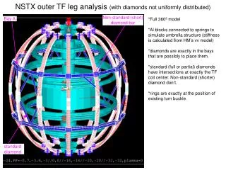
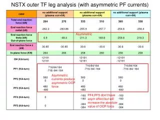
EM Force Distribution In Flags • Spark Model Also Used to Determine EM force distribution in Flag from TF Field • Out of Plane forces from PF not repeated at this time. • Forces Calculated for split flag configuration • Resultant forces predominately vertical with 1/R distribution • Forces not recalculated for solid flag, but • Vertical forces should still have same 1/R behavior and magnitude • Radial forces should be larger in flag and should work to keep joint closed
Note: Jump in loads at ends results from change in FEA mesh density
Summary • Thermal distributions and EM loading provided as input to Structural Analysis being performed and presented by Irv Zatz