Download
1 / 18
180 likes | 264 Views
This review covers requirements, forces, load paths, temperatures, thermal effects, and more in the design of the NSTX TF flag joint. It includes detailed information on field and current requirements, current waveforms, number of pulses, thermal cycles, voltages, EM forces, and key design features. The design highlights solid flags with Kapton layers, torque collars, voltage probes, and more. This comprehensive review ensures a robust and efficient design for the NSTX TF flag joint.

E N D
Topics • Requirements • Forces • Load Paths • Temperatures and Thermal Effects • Contact Resistance • Features of New Design
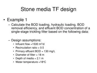
FIELD AND CURRENT • Base GRD requirement: 3kG at R0=0.854m with 4.5 sec flat top, once every 300s 35580 Amp with 36 turn coil • High field GRD requirement: 6kG at R0=0.854m with 0.6 sec flat top, once every 300s 71160 Amp with 36 turn coil
CURRENT WAVEFORMS • Engineering design accounts for PS response, inc’l L/R decay in case of fault from Imax • ∫I2T = 6.0 x 10⁹ A2-s for 3kG-4.5s • ∫I2T = 6.15 x 10⁹ A2-s for 6kG-0.6s • Design basis ∫I2T = 6.5 x 10⁹ A2-s which causes adiabatic T of 80oC in Cu • 6kG pulse is most critical for joint since forces are maximum and time for heat diffusion is minimum
NUMBER OF PULSES & THERMAL CYCLES • Assume 50,000 pulse requirement at 6kG • 10 yr*20 week*5day*8hr*6pulse/hr = 48,000 • Highly conservative • NSTX 5yr plan calls for ≈ 5% 6kG pulses plus… • 40% @ 3kG (25% EM load) • 40% @ 4kG (44% EM load) • 15% @ 5kG (69% EM load) • Assume 1,000 thermal ratcheting cycles (= number of days) • 10 yr*20 week*5day = 1000 • drives flag fastener fatigue cycle requirement • assuming 12 pulse/hr rate to set thermal ratcheting (conservative)
VOLTAGES • TF PS is 1kV DC no-load • 1012.85 volts DC avg • 1060 volts peak • High resistance grounded, Vline-ground=500V nominal, 1kV max • CHI can elevate hub assembly and OH tension tube to 1kV • Max design voltages: • turn-to-turn = 1000/36 ~ 30V for adjacent conductors, 1kV max • turn-to-ground (hub and OH tension tube) = 2kV • base hipot = 2E+1= 5kV • routine hipot ~ 3kV
EM FORCES • In-Plane • vertical load and moment • due to magnetic pressure • from self-field • Out-of-Plane • lateral due to ItfxBz(oh&pf) • torsional due to ItfxBr(oh&pf)
IN-PLANE FORCES Notes: Bt=6kG Forces include accumulation midway through flex link
OUT-OF-PLANE FORCES Notes: Bt=6kG OH and all PF at maximum current OH contribution is bi-directional
LOAD PATHS Friction Shear Shoe Torque Collar Hub/Spline/VV
TEMPERATURES • • Inner Leg • - TSOFT = 29oC • - TEOFT = 66oC • TEOP = 95oC (worst case) • • Wet lay-up & collar • - negligible T
THERMAL EFFECTS • Vertical length of inner leg bundle from bottom to top increases by up to 0.35” during a pulse • Vertical length of inner leg from torque collar to top of bundle increases due to inner leg temperature rise, whereas flag and hub remain relatively cool • Radius of inner leg bundle increases bundle increases by approximately 0.006” during a pulse • Flag heats modestly during pulse (T ≈ 5oC) but can ratchet to T ≤25oC at rated duty cycle (conservative), r ≈ 0.005” in length
CONTACT RESISTANCE Tolerable Resistivity ≈ 2.5µΩ-in2 (700psi) Req’d Flat Top Time =0.6 sec Note: assuming constant resistivity along joint
Shear Shoe Hub Disk Flag bolt (stud) Probe Tail Flag Box Flag Collar Box Bolt (stud) KEY DESIGN FEATURES
VOLTAGE PROBES • • IDI 100526 Coax Probe terminated in SMB connector • commercial spring loaded probe used in semiconductor test industry
DESIGN HIGHLIGHTS • Solid flags w/2 half-lapped layers Kapton, glass wrapped, potted in 304SS boxes • Boxes bolted to the hub disks using 5/8” hardware • Flags attached via 3/8” Inconel bolts (studs) preloaded to 5000lbf • Shear shoe on outer edge of flags is bolted to ends of inner leg conductor using Inconel bolts, one vertical and one angled for moment reaction • 3-segmenttorque collar w/two 1/2” A286 bolts/6000lbf belleville washers per joint, 0.180” wet lay-up (Hysol E-120HP), 1ksi min. compression • Collar transmits torque to hub structure at 3 anchor points • Redundant voltage probes are located on each side of the flag