PLASMA AIDED DIELECTRIC ETCHING
PLASMA AIDED DIELECTRIC ETCHING. Guoyun Tian Electrical and Computer Engineering Auburn University February 21, 2001. Outline. Introduction Components for Dielectric Etching Evaluation of Etching Processes Etch Gases Highly Anisotropic Etching Isotropic and Anisotropic Etching.

PLASMA AIDED DIELECTRIC ETCHING
E N D
Presentation Transcript
PLASMA AIDED DIELECTRIC ETCHING Guoyun Tian Electrical and Computer Engineering Auburn University February 21, 2001
Outline • Introduction • Components for Dielectric Etching • Evaluation of Etching Processes • Etch Gases • Highly Anisotropic Etching • Isotropic and Anisotropic Etching
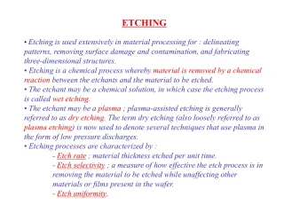
Introduction • Plasma etching is a dry etching method. • It overcomes problems such as contamination, waste disposal caused by wet chemical etching. • It can result in highly anisotropic etching. • A desired etch feature can be achieved by a combination of isotropic and anisotropic etching. • High etch rate and selectivity can be achieved by manipulating the etch gas mixtures.
Categories of Dry Etching Methods( John L. Vossen, Aerner Kern, Thin Film Processes II, Academic Press Inc.) Laser assisted etching Reactive gas etching Dry etching “Beam methods” Ion beam methods Glow discharge methods Down stream etching ECR etching Ion milling Reactive ion beam etching Sputter etching RIE Barrel Ion beam assisted chem. etch. Parallel plate plasma etching Etching mainly by reactive neutrals Pressure range 0.2 – 2 Torr 0.01 - 0.2 Torr 0.1 - 1Torr 10-4-10-3 Torr 10-4-10-1Torr Energy of ion bombard Low High Minimal High, but adjustable
Components of Dielectric Etching • Power Supply: RF and/or MW • Etch Gases: Halogen-containing gases. Fluorocarbon gases are preferred • Dielectric Materials: oxides, nitrides, polymers, low-k dielectrics etc. • Chamber Systems:
Evaluation of Etching Processes • Uniformity: • Selectivity: • Etching Rate:
Uniformity • Gas Flow: location (the relative position of gas inlet and pumping port has to be optimized for the given reactor geometry); rate (at certain minimum level with respect to the desired etch rate) • Bull’s Eye Effect: corresponding appearance of interference colors of reflectivity on an incompletely etched wafer because the relative reactivity of wafer surface with respect to electrode. • Edge Effect: wafer should be placed far away from the edges of electrode. Edge effect results in non-uniformity by changing sheath thickness as well as varying angles of incidence. • Loading Effect: use dummy wafer; increase flow rate; promoting wall reaction
Selectivity • Carbon Blocking: The increased selectivity is mainly due to carbon-containing species originating in the fluorocarbon glow discharges and accumulating on the surface. Using gas mixtures with H2 to form HF to prevent reactions with carbonaceous species; Using gas mixtures with higher C/F ratio; Using a scavenger for fluorine such as third silicon electrode or silicon-containing gas to form volatile silicon-fluorine compounds that can be removed. • Volatility: Materials that form volatile compounds in a glow discharge etch much faster than the materials that are converted to involatile compounds, such as etching photoresist on Si, SiO2, Al in a O2 plasma. • Thermodynamics: Etch processes with large negative free energy of reaction H are usually much faster, such as Al etches much faster than SiO2 in a Cl2 plasma.
Etching Rate • Gas Flow Rate: Etching rate first increases with gas flow rate, reaches maximum, and then decreases. • Gas Additives: Add gases such as O2 to react with free radicals in the fluorocarbon gas system to release fluorine and increase etch rate.
Etching Gas Systems • Straight-chain low fluorocarbon gas system: such as CHF3, CF4/O2, CF4/NF3, or CHF3/CF4/He; • Straight-chain higher fluorocarbon gas system such as C2F6, C3F8, C4F10, or C4F8; • Cyclic high fluorocarbon system: saturated fluorocarbon compound c-CnF2n such as c- C3F6, or c- C4F8; and non-saturated fluorocarbon compound c-CnFy (y<=2n-2) such as c-C3F3 or c-C4F6. The schematic view of c- C3F6 and c-C4F6, F entered at the center of a carbon ring indicates that the hydrogen atoms of each of the hydrocarbon compounds having the same carbon skeletons are unanimously substituted by fluorine atoms. c- C3F6 all bond saturated c-C4F6 containing one unsaturated bond
Highly Anisotropic Etching Silicon Nitride Patterned Photoresist Remote and In-situ Plasma Etching Oxide After Remote Plasma Etching Lowenstein, U.S. Patent 4857140(1989) Method for Etching Silicon Nitride
Etching Equipment Wafer carrier Electrode Process chamber Etchant: Fluorine source C2F6, NF3, CHF3, and SF6with He, H2 Gas distributor Pipe from remote plasma to chamber Second gas distributor Remote plasma generator (MW) Electrode (RF) H2 bypass can increase selectivity but will reduce the etch rate to the directly passing through the generator In-situ plasma combining with remote plasma increase etching rate Vacuum pump
Cyclic high fluorocarbon system to Form Contact Hole in SiO2 Yanagida, U.S. Patent 5338399 (1994) Dry Etching Method Patterned resist Dielectric Substrate Diffusion layer c- C4F8 vs C3F8 Resist selectivity: 3.5 vs 1.5 Silicon selectivity: 7.2 vs 3.9 c-C4F6 vs c- C4F8 Resist selectivity:4 vs 3.5 Silicon selectivity: 12 vs 7.2 Higher C/F ratio The C3F8 and c- C4F8 mixed gas composed mainly straight chain C3F8 were also used to achieve high etching rate and high selectivity. RF with 2 MHz frequency and Magnetic strength field about 150 Gauss. The proper gas pressure and flow rate were used.
Third electrode Selective Etching of Oxide over Nitride Matching network Gas inlet Antenna tuned to resonance for inductively coupling Top wall Chamber housing Plasma source Side wall(anode) Substrate processing Bottom wall Substrate support electrode (cathode) Vacuum system Pressure 5 mtorr – 50 mtorr, Etchant: CF4, C2F6, C3F8 Reduce the amount of fluorine in the plasma so that reducing the decomposition of ploymer to increase the selectivity Marks et al. U.S. Patent 5423945 (1995) Selectivity for Etching an Oxide over a Nitride
Combination of Isotropic and Anisotropic Etching Contact hole Patterned PR Oxide Sloped walls Ploy-crystalline Si Etchants: Isotropic– carbon tetrafluoride(CF4), and/or ammonium trifluoride(NF3) mixed with O2 ; Anisotriopic: carbon tetrafluoride mixed with trifluoromethane and argon or helium or nitrogen. As the etching proceeds, the content of fluorine atoms is adjusted to in favor of the formation of free radicals and ions with simultaneously reducing the spacing of electrode. Generating contact holes with beveled sidewalls in intermediate oxide layer, PN4764245 (1988)
Continued PatternPR Dielectric Substrate Underlayer(Polisilicon, diffusion or conductive layer) The low L/V ratios and angles don’t allow the uniform filling of the etched features, resulting in formation of overhangs at the edges and corners of the etched features. Voids and gaps can be formed during the following deposition. Preferred L/V ratio is 0.6-1.4, average angles of less than about 90°C. Passivating deposit
Preferred Equipment for Etching Special Feature Shape Impedance matching to plasma zone Microwave applicator Plasma zone Gas distributor Process zone Substrate Merry et al., U.S. Patent 6015761 (2000) Microwave-activated etching of dielectric layers,
Processes for fabricating complex sidewalls • Process gas composition and process conditions to etch features having particular shape depend on the composition of dielectric layer. • Process gases comprises (i) fluorocarbon gases (all those straight chain gases and/or their mixtures) for providing fluroride-containing dissociated species that etch the dielectric layer. (ii) inorganic fluorinated gases (NF3, SF6, HF), that enhances dissociation of the flurocarbon gas, and/or reduces the recombination of dissociated fluorine-containing species during transport of plasma.(iii) O2 for controlling the the amount of passivating deposits formed on the substrate to provide highly isotropic etching. Their volumetric flow ratio are primary factors in controlling the shape of etched features • The recombination of dissociated species F to non- dissociated F2 results in slower dielectric etching rates and reduced the isotropic etching.