Lecture 8 – Plasma Etching
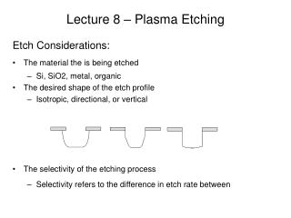
Lecture 8 – Plasma Etching. Etch Considerations: The material the is being etched Si, SiO2, metal, organic The desired shape of the etch profile Isotropic, directional, or vertical The selectivity of the etching process Selectivity refers to the difference in etch rate between .

Lecture 8 – Plasma Etching
E N D
Presentation Transcript
Lecture 8 – Plasma Etching Etch Considerations: • The material the is being etched • Si, SiO2, metal, organic • The desired shape of the etch profile • Isotropic, directional, or vertical • The selectivity of the etching process • Selectivity refers to the difference in etch rate between
“trenching” + Plasma Etching 1) Physical sputtering with no chemical reactions and high energy (Ar sputtering) Corners are rounded, sidewalls generally reflect ions forming “trenching” near edges, etch profile is directional. “Mask” material tends to: 2) Reactive Ion Etching (RIE) plasma ionizes reactive species (O2 plasma) Sidewalls are etched back with rounding, trench bottoms generally smooth and flat, reactive species are etch profile is mostly
notching – undercutting of mask + + + Plasma Etching - Cont 3) Ion enhanced RIE uses ions to energetically excite chemical active species (Ar ions to kinetically excite chlorine gas to etch GaAs) Sidewalls are etched back, bottom curved, some “notching” can occur, etch profiles are mostly vertical 4) Ion enhanced RIE with inhibitor-ions are used to excite both chemically reactive species and inhibitor (ICP uses argon to excite SF6 into etching Si and transforming C4F8 into a Teflon like polymer to coat sidewalls) Polymer “inhibitor” layer deposited everywhere, but along trench bottom removed faster than deposited, along sidewall visa versa. Highest aspect ratio (channel depth/width) and most vertical etching achieved this way.
Simple Etch Chambers Types of plasma etching tools include, • Barrel reactor • Substrates are shielded to reduce exposure to energetic particles • Downstream etching • Reactant generation and stripping take place in two different zones • Parallel-plate system • Substrates are placed inside the plasma leading to higher ion damage as compared with the other two methods
Reaction Mechanisms There are six primary mechanisms, • Reactive species are produced in the gas phase (by plasma or energy transfer) • Reactive species diffuse to the surface • Reactive species adsorb onto the surface • Propagation until reaction • Desorption from the surface of reaction byproducts • Diffusion away from the surface into the bulk gas
Reaction Mechanism Notes: • The overall reaction rate is determined by the slowest rate step. • Desorption species can adversely effect reaction rate by becoming ionized in the plasma and re-interact with the sample surface (called byproduct re-cycling). Increasing gas feed and exhaust rates along, or lowering the chamber pressure generally can reduce this. • Desorption and surface reactions (e.g. bond breaking) are generally assisted by ion bombardment of the sample (typically Ar+) • Typically increasing the substrate temperature will help volatilize (desorb) reaction byproducts, especially if this is a rate limiting step. Conversely, decreasing substrate temperature usually improves surface adsorption of reaction species (and polymerization).
Plasma Reactions – Example 1 Silicon etching using the gases: Ar and CF4 1. The primarily ions are: Neutral radicals are produced in smaller quantities and are: 2. Assuming the substrate is biased, then ions are accelerated toward the sample and ions are generally repelled. The uncharged radicals will diffuse toward the surface and are the primary etch species. 3. absorption 4. first reacts with exposed dangling bonds at the surface, then more radicals start breaking the substrate bonds. • desorbs (desorption is assisted by ion bombardment of and ions) • Volatile products diffuse away from the surface
Plasma Reactions – Example 2 Si3N4 etching using CF4 and Argon 1. 7 Product produced by plasma: 2. Ions accelerated toward cathode: 3. Ions diffuses toward cathode: 4. Ion decelerated toward cathode: 5. Primary reactive species: 6. Desorption from surface of primarily 3 byproducts: 7. Primary ion that assist with desorption:
Plasma Reactions – Example 3 Polymer etching using Oxygen and Argon 1. 5 Product produced by plasma: 2. Ion accelerated toward cathode: 3. Ion diffuses toward cathode: 4. Ion decelerated toward cathode: 5. Reactive species: • Desorption from surface of what 3 byproducts: • Ion that assist with desorption:
Reaction Mechanisms – Notes Points to consider: • Homogeneous reactions occur in the gas phase • Plasma creates highly reactive species • Radicals are more abundant than ions • Neutral radicals have a longer lifetime • Heterogeneous reactions form on the surface • Reactions in the plasma may affect the reactions on the surface • Radicals produced in the plasma may increase reaction with the surface • Non-reactive species may block surface sites decreasing reaction
Etching Loading Effects A loading effect occurs when the amount of etchant is being depleted by the exposed area to be etched (i.e. amount of reactant). • The etch rate is (roughly) inversely proportional to the exposed silicon • The more chemical the etching, the bigger the loading effect • At lower pressures, this effect becomes smaller • Uniformity is compromised by an etch rate dependant on loading • Gas flow and residence time (the average length of time a molecule of gas spends in the chamber) are now much more important in the overall uniformity of the etching process Low loading High loading
Etching Rules – F/C ratio 1. Fluorine to carbon (F/C) ratio when etching Si • When fluorine and carbon are both present, etching and polymerization occur • Etching is caused by the fluorine and polymerization occurs due to the hydrocarbons • The lower the ratio, the slower the etching • Adding hydrogen the F/C ratio and also the etch rate • Adding oxygen the F/C ratio and also the etch rate • oxygen also aggressively attacks the resist • Gases like NF3 and ClF3 allow higher fluorine concentrations but doesn’t attack the resist
Etching Rules – Polymerization Point 2. Polymerization point: • The polymerization point is when the polymer removal rate is equal to the polymerization rate • A better selectivity is achieved closer to the polymerization point • Factors that increase the polymerization rate (and selectivity) include temperature, hydrogen concentration, plasma power, chamber pressure, and monomer concentration • To achieve high selectivity with organic (resist) masks, one must operate close to the polymerization point because any loss in resist can be compensated for by redeposition of reaction products • Any additional oxygen will severely decrease
Etching Rules – Metal Etching 3. Metal etching • Chlorocarbons and fluorocarbons are typically used to etch metal films • Native metal oxides greatly reduce etch rates and must be removed. • The presense of oxygen and water vapor greatly metal etch rates. • Ion bombardment is due to the strong metal oxide bond
Triode Reactor Designs Motivation – for diode plasma system to increase etch rate, we must increase RF power, but this also increases the kinetic energy of the bombarding ions, which causes: • Mask erosion • Device damage • Particulate contamination • Surface heating • Secondary sputtering Thus the triode setup seeks to achieve high etch rates but at low ion impact energies. • Examples (three categories: IBE, ICP and ECR)
Gas Inlet ~ RIBE creates plasma with reactive gas Accelerating Electrode (-V) Neutralizing Filament CAIBE adds a reactive gas at the sample ~ Exhaust IBE (Ion Beam Etching) CAIBE adds the reactive gas at the sample so that gas will not etch or erode the chamber and so ionized gas will not be repelled by negatively biased substrate IBE Advantage: IBE Disadvantage:
Gas Inlet ~ ~ Exhaust ICP (Inductively Coupled Plasma) Top helical RF coil creates the plasma. Substrate RF determines accelerating bias. ICP has produced the highest plasma densities and highest etch rates
Gas Inlet Microwaves Microwave window ~ Exhaust ECR (Electron Cyclotron Resonance) Microwaves (very high frequency waves) are absorbed by the gas species and become ionized forming a plasma ECR Disadvantage – mode hoping and plasma nonuniformities.