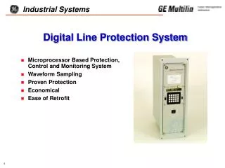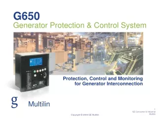
Digital Generator Protection System
Digital Generator Protection System. Microprocessor Based Protection, Control and Monitoring System Waveform Sampling User Friendly GE/Hydro Quebec Joint Development. System Overview. Multiple Microprocessors Sampling Rate = 12 Samples/Cycle 20 MHz Operation


Digital Generator Protection System
E N D
Presentation Transcript
Digital Generator Protection System • Microprocessor Based Protection, Control and Monitoring System • Waveform Sampling • User Friendly • GE/Hydro Quebec Joint Development
System Overview • Multiple Microprocessors • Sampling Rate = 12 Samples/Cycle • 20 MHz Operation • Auto Gain Change A/D Converter DSP’S 3-TMS320 MICROPROCESSORS 2-80C186 8 CURRENTS ANALOG TO DIGITAL CONVERTER FILTER AND MUX REMOTE PC 4 VOLTAGES MMI TIME SYNCH (IRIG-B) 4 TRIP RELAYS DIGITAL INPUTS/ OUTPUTS 6 CONTACT INPUTS 11 AUXILIARY RELAYS
Applications • For Small, Medium and Large Generator Protection • Suitable for Variety of Prime-Movers - Gas, Steam, Hydro Turbines • Most Commonly Used Protection Functions Packaged in a Standard Modular Case
Protective Functions (87G) • Stator Differential (87G) • Variable Slope Characteristic • 100% Stator Ground Fault (64G) • Two Overlapping Zones • 95% with Fundamental Neutral OV • 15% with 3rd Harmonic Comparator • or 15% with 27TN Function (Special) • Time Overcurrent with Voltage Restraint (51V) • Current Unbalance (46) • Negative Sequence Overcurrent - I22t • Linear Reset Characteristic • Loss of Excitation (40) • Two Zones of Off-Set Mho (40) X R Offset = X’d 2 Diameter = 1.0 pu Diameter = Xd
Protective Functions (Cont.) (24) VOLTS/HERTZ (%) • Overexcitation or V/Hz (24) • Inverse Characteristic • Instantaneous with Time Delay • Reverse Power (32) • Two Levels • Under/Over Frequency (81) • Multiple Steps (2-4) • Undervoltage Cutoff Feature • Overvoltage (59) • Inverse Characteristic • Undervoltage (27) • Neutral Overcurrent (51GN) Transformer Limit Curve on Generator Voltage Base 140 130 Generator Manufacturer’s Recommended Protection Curve 120 110 Relay Characteristic 100 .01 0.1 1.0 10 100 TIME (MINUTES)
Additional Protective Features • Voltage Transformer Fuse Failure (VTFF) • Internal or External • Block 40 and 51V functions
Additional Protective Features • Accidental Energization Logic • Sequential Trip Logic
(8) Currents Ia, Ib, Ic, In(Neutral Side) Ia, Ib, Ic, In(System Side) (4) Voltages Va, Vb, Vc(Wye or Open Delta) Vng(Neutral Ground Xfmr) IRIG-B Time Synchronization (6) Digital Inputs Two External Trip (DI3, DI4) Generator Off-Line Indication (AE) Turbine Inlet Valve Close Indication (Sequential Trip) Oscillography Trigger External VT Fuse Failure Inputs
Outputs • (4) Trip Relays • Two From A Contacts Each • Configurable • (11) Auxiliary Relays • One Form C Contact Each • Four Configurable Alarm Contacts (74A, 74B, 74C, 74D) • Pre-defined Alarm Contacts • Critical Self-Test Alarm • Non Critical Self-Test Alarm • VT Fuse Failure Alarm • Test Pickup Indication • Test Trip Indication • Loss of Power Supply No. 1 • Loss of Power Supply No. 2
Stator Differential (87G) TRIP A Accidental Energization (AE) OR 94G Reverse Pwr.(32-1, 32-2) Overvoltage (59) TRIP B OR 94G1 Undervoltage (27) Overcurrent with voltage restraint (51V) TRIP C OR 94G2 Current Unbalance - Trip, Alarm (46T, 46A) TRIP D Loss of Excitation (40-1, 40-2) OR 94G3 Stator Ground - Zone 1, 2 (64G1, 64-2) ALARM Neutral Overcurrent (51GN) OR 74A CONFIGURABLE LOGIC Overexcitation, Trip (24T) ALARM Generator On-Line OR 74B Overexcitation, Trip (24T) Generator Off-Line ALARM OR 74C Under Frequency (81-1U, 2U,3U,4U) ALARM Over Frequency (81-1O, 2O,3O,4O) OR 74D Simplified Logic Diagram
Monitoring • Present Values • Trip Circuit Monitor • Fault Reports (Last 3 Faults) • Sequence of Events(Last 100 Events) • Self Tests
Present Value Monitoring • Currents • System and Neutral Side (Ia, Ib, Ic, In) • Negative Sequence • Voltages • Va, Vb, Vc • % 3rd Harmonic Voltage (Phase and Neutral) • Megawatts • Mvars • Frequency • Status of Digital Inputs Scroll on Command or Display Selected Parameters
Trip Circuit Monitor • Trip Voltage Monitor • Normal Condition • Four Trip Circuits (94G, 94G1, 94G2, 94G3) • Trip Current Monitor • Trip Condition • Four Trip Circuits (94G, 94G1, 94G2, 94G3) • Seal-in of Output Relay • Disable/Enable Feature
Communications • Local MMI (Standard) • 2 Level Password Protection • 16 LED Alphanumeric Display • Keypad with 20 Keys • Separate Function Keys for • Settings • Action • Information • 19 LED Targets • Status LED • Local Printer Port (AA, CA models)
[ - ] DGPCOMMUNICATIONS 1.35 Local FunctionsSetupHelp Relay Functions Logout Change access level Hang up phone Actions . . . Information . . . Settings . . . Login Phone disconnected Communications • Remote Access • Via RS232 & “DGP-LINK” Software • Front and Rear RS232 Ports • 3 Level Password Protection • Access to: • Present Values • Fault Report • Sequence of Events • Oscillography • Manual Control • Relay Settings
Present Values • Currents • Voltages • Watts • Vars • Frequency • Negative Sequence Current • 3rd Harmonic Voltage • Status of Digital Inputs GEN Simulator DGP 0000 PRESENT VALUES Station ID:MALVERN Generator ID:MODEL GENERATOR 10/28/93 14:37:23:446 IAS: 5696.0 A -014 DEGS VAN: 008.5 KV 000 DEGS IBS: 5488.0 A -142 DEGS VBN: 008.1 KV -118 DEGS ICS: 4864.0 A 104 DEGS VCN: 008.2 KV 122 DEGS IAR: 5680.0 A -014 DEGS IBR: 5456.0 A -142 DEGS ICR: 4880.0 A 104 DEGS NEGATIVE SEQ CURRENT: 08.1 % 3RD HARM PH: 00.1 % 3RD HARM N: 03.7% WATTS: +126.33 MWATT VARS: +041.95 MVAR GEN OFF-LIN: OPEN INLET VLV: OPEN DIG IN 3: OPEN DIG IN 4: OPEN OSC TRIG: OPEN EXT VTFF: OPEN FREQ: 60.00 SAMPLING FREQ: 720.0
Fault Report Gen Simulator DGP 0000 FAULT REPORT Station ID:MALVERN Generator ID:MODEL GENERATOR FAULT#: 02 FAULT DATE: 08/09/93 TRIP TIME: 05:10:37:829 FAULT TYPE: ABC TRIP TYPE: 87G SYSTEM OPERATING TIME: 000008 PREFAULT FAULT -------------------------------------- ------------------------------------------------------ IAS: 0128.0 A IAS: 014672 A IAR: 015664 A IBS: 0208.0 A IBS: 015264 A IBR: 016704 A ICS: 0080.0 A ICS: 013600 A ICR: 014960 A INS: 0048.0 A INR: 0384.0 A VAN: 010.2 KV VBN: 010.2 KV VAN: 693.0 V VCN: 010.0 KV VBN: 693.0 V VCN: 679.4 V FREQ: 60.00 VN: 047.0 V WATTS: +1888.5 KWATT VARS: +3777.0 KVAR 05:10:37.834 87G PHASE A ON 05:10:37.834 87G PHASE B ON • Prefault • Currents • Voltages • Watts • Vars • Frequency • Post Fault • Currents • Voltages • Trip Targets • Operating Time • Selected Events • Last 3 Faults Stored
Sequence of Events • Operational Events • Setting Changes • Fault Data • Status • Diagnostic Self-Test Events • Warning (Non-Critical Alarm) • Failure (Critical Alarm) • Time Tagged to 1ms Resolution • Last 100 Events Stored • Available at Communication Port or at Printer Port GEN Simulator DGP 0000 Events Station ID:MALVERN Generator ID:MODEL GENERATOR 10/29/93 14:39:54:971 94G TRIP CIRCUIT OPEN ALARM ON 10/29/93 14:33:35:661 94G2 TRIP SIGNAL RESET 10/29/93 14:33:35:660 32-1 OFF 10/29/93 14:33:35:639 32-2 OFF 10/29/93 14:33:34:396 32-1 ON 10/29/93 14:33:31:997 TURBINE INLET VALUE CLOSED 10/29/93 14:33:28:423 GENERATOR OFF-LINE 10/29/93 14:33:26:452 94G2 TRIP SIGNAL ON 10/29/93 14:33:26:451 32-2 ON 10/29/93 14:27:09:878 GENERATOR ON-LINE 10/29/93 14:27:04:968 TURBINE INLET VALUE OPEN 10/29/93 14:26:54:263 94G3 TRIP SIGNAL RESET 10/29/93 14:26:54:262 64G1 OFF 10/29/93 14:26:50:911 TURBINE INLET VALUE CLOSED 10/29/93 14:26:47:584 GENERATOR OFF-LINE 10/29/93 14:26:42:604 94G3 TRIP SIGNAL ON 10/29/93 14:26:42:603 64G1 ON 10/29/93 14:25:44:444 GENERATOR ON-LINE 10/29/93 14:25:38:202 TURBINE INLET VALUE OPEN 10/28/93 16:32:31:642 REMOTE - SETTINGS CHANGE DONE 10/28/93 16:32:30:882 REMOTE - SETTINGS CHANGE STARTED
Sequence of Events • Events Include: • Trip Signal ON / RESET • Protection Function ON / OFF • Digital Input Status • VT Fuse Failure Alarm ON / OFF • Trip Circuit Open Alarm ON / OFF • Trip Circuit ENERGIZED / NOT ENERGIZED • Password Changed • ENABLE / DISABLE Outputs • Setting Change START / DONE • Failure Messages (Critical Self-Test Alarm) • Warning Messages (Non-Critical Self-Test Alarm)
Oscillography Data • Currents and Voltages • Digital Flags • Internal and External Oscillography Triggering • 120 Cycles of Storage Capability • Up to 20 Cycles Prefault Data • Up to 3 Trip Event Captures • ASCII File Format(Readable by EXCEL/LOTUS/DGP-DATA) • Fault Report and Settings Saved for Each Fault
Hardware and Packaging • Testing and Trouble Shooting • Optional MOD-10 Modular Test and Connection Plugs for Current/Voltage Injection • Draw-Out Modular Construction • Plug-In Modules for Test and Maintenance • Removable Door • Target Clearing Through Door • Self-Test Diagnostics • Critical Alarm • Non-Critical Alarm
Nomenclature Selection Guide DGP * * * A * * 1 1 AMP Rated 5 5 AMP Rated 0 One power supply, 48 Vdc 1 One power supply, 110/125 Vdc 2 One power supply, 220/250 Vdc 3 Two power supplies, 48 Vdc 4 Two power supplies, 110/125 Vdc 5 Two power supplies, 220/250 Vdc A With Test Blocks B Without Test Blocks A Future Use A Function Group A See B Function Group B DGP Selection C Function Group C Guide A Revision Level
DGP Selection Guide FUNCTIONS & FEATURESA B C Stator Differential 87G X X X Current Unbalance 46 X X X Loss of Excitation 40-1, 40-2 X X X Anti-motoring 32 2 Setpoints 1 Setpoint 2 Setpoints OC - voltage restraint 51V X X X Stator Ground 64G1 (Fundamental OV) X X X Stator Ground 64G2 (3rd Harm. Comparator) X - X Neutral OC 51GN - X X Over Excitation 24 (Volts/Hz) X X X Over Voltage 59 X X X Under Voltage 27 - X X Under Frequency 81-U 4 Setpoints 2 Setpoints 4 Setpoints Over Frequency 81-O 4 Setpoints 2 Setpoints 4 Setpoints Accidental Energization Logic X X X Sequential Trip Logic X X X Voltage Transformer Fuse Failure VTFF X X X Oscillography Data Capture X - X Communication Ports 2-RS232 2-RS232 2-RS232 Printer Output X - X IRIG-B Input X - X Example: DGP54BACA - DGP rated 5 amperes, 50/60 Hz, 110/125 VDC redundant power supplies, no built-in test blocks, function group A, revision A.