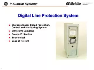
Digital Line Protection System
Digital Line Protection System. Microprocessor Based Protection, Control and Monitoring System Waveform Sampling Proven Protection Economical Ease of Retrofit. ON. SET. 1/Y. 2. 3/N. CLR. Power. 1. INF. 4. 5. 6. 0. OFF. ACT. 7. 8. 9. END. PRT. 0. ENT. COMM.

Digital Line Protection System
E N D
Presentation Transcript
Digital Line Protection System • Microprocessor Based Protection, Control and Monitoring System • Waveform Sampling • Proven Protection • Economical • Ease of Retrofit
ON SET 1/Y 2 3/N CLR Power 1 INF 4 5 6 0 OFF ACT 7 8 9 END PRT 0 ENT . COMM DLP-D Enhancements Three Phase & Single Phase Tripping Continuous Monitor Alarm 2 Shot Recloser Optional ASCII SUBSET gDigital Line Protection GREEN: PROTECTION ON RED: CHECK STATUS Proven Design DLP-C Repackaged TRIP AC Z1 50 GE PROTECTION AND CONTROL Malvern, PA MODEL DLP3512CDH Ratings: In 5 AMPS Vn 120 Vac Freq 60 Hz GEK 99300 Unbalance Alarm Detection New Packaging 3 RU High Horizontal or Vertical SCADA Involved Phases Indication Standard Carrier Start Options
SETTINGS ANALOG TO DIGITAL CONVERTER MicroP’s & EPROMS MMI I DISPLAY V RS232 RECURSIVE FOURIER TRANSFORM PHASOR QUANTITIES EMULATION OF: PHASE ANGLE COMPARATORS, AMPLITUDE COMPARATORS, ETC. MEASURING FUNCTIONS LOGIC OUTPUTS Overview of DLP Operation • Multiple Microprocessors (3) • Sampling Rate = 16/Cycle
DLP Application • For Three Phase or Single Phase Tripping on any Uncompensated Transmission Line • Typical Operating Times are 3/4 to 1-1/2 Cycle • 6 Protection Schemes • Step Distance • Directional Comparison Blocking • POTT • PUTT • Hybrid • Zone 1 Extension
DLP Operating Times • SCR Tripping Times • PT Potential Source
DLP Operating Times • SCR Tripping Times • CVT Potential Source
Settings: • Scheme Selection • STEP • POTT • PUTT • HYBRID • BLOCKING (BLK1, BLK2, BLK3) • ZONE 1 EXTENSION • Zone 2 Ground Measuring Unit Selection • Distance • Directional Overcurrent • Distance + Directional O/C
Measuring Functions DISTANCE Phase Ground Zone 1 MHO MHO-or-REACTANCE Zone 2 MHO MHO (Pilot Zone) Zone 3 MHO MHO Zone 4 MHO* MHO (Reversible/Blocking) *Settable Offset
Measuring Functions OVERCURRENT (3|I0| - KT|I1|) IPT - Pilot Trip (3|I0| - KB|I1|) IPB - Pilot Block IT - Trip Supervision IB - Block Supervision FD - Fault Detector (3|I0| - KD|I1|) IDT - Inst. Direct Trip (Directional Control) (3|I0|) GTOC - Time Overcurrent (Directional Control) DIRECTIONAL NT - Trip NB - Block
? Ground TOC Curves Inverse Very Inverse • Custom Ground TOC Curves From Several Sources • Curves generated by GE’s TOC curve editor • Any curve from GE’s TOC curve database • The Existing Library of ASPEN RelayEditorTM curves • Any custom curve designed with ASPEN RelayEditorTM Custom Extremely Inverse Definite Time
Additional Protective Relay Features • Out-of-Step Blocking • PT Fuse Failure • Line Pickup (Close Into Fault) • Remote Open Detector • Line Overload • Adaptive Reach(Zone 1 Ground Reactance - Supervising MHO) • Current Unbalance Alarm • Continuous Monitor Alarm Detects Internal Relay Changes if FD is Not Picked Up • Carrier Start Options for Improved Coordination in Blocking Schemes with Other Relays. • Trip Bus Check when Settings are Changed
Recloser (Optional) • Single breaker reclosing • Programmable up to 2 reclose attempts • Manual Lockout Panel Switch • Additional Inputs • Reclose Initiate, Reclose Inhibit, Reclose Cancel, Reclose Reset • Additional Outputs • Zone 1 Reach Reset, Lockout Alarm, Reclose in Progress
IA, IB, IC VAG, VBG, VCG RI-1P RI-3P Receiver 1 Output Contact Receiver 2 Output Contact* Stop Carrier* Block Pilot Tripping* (3) 52/b Contacts (w/ Recloser) (3) 52/b Contacts (w/o Recloser) Reclose Inhibit Reclose Cancel Reclose Reset 3 Pole Trip Enable * Configurable Inputs Inputs - Single Phase Models
IA, IB, IC VAG, VBG, VCG (6) Digital Inputs (Contact Converters) (2) 52/b Contacts Receiver 1 Output Contact Receiver 2 Output Contact* Stop Carrier* Block Pilot Tripping* RI** Reclose Inhibit** Reclose Cancel** Reclose Reset** * Configurable Inputs ** Inputs for Recloser Inputs - Three Phase Models
Configurable Inputs (1701) CONCCI CC4 CC5 CC6 0 RECEIVER 2 SELECT GROUP BIT 1 SELECT GROUP BIT 0 1 EXTERNAL TRIGGER SELECT GROUP BIT 1 SELECT GROUP BIT 0 2 CONFIG. INPUT 1 SELECT GROUP BIT 1 SELECT GROUP BIT 0 3 RECEIVER 2 STOP CARRIER BLOCK PILOT TRIP 4 EXTERNAL TRIGGER STOP CARRIER BLOCK PILOT TRIP 5 CONFIG. INPUT 1 STOP CARRIER BLOCK PILOT TRIP 6 RECEIVER 2 CONFIG. INPUT 2 CONFIG. INPUT 3 7 EXTERNAL TRIGGER CONFIG. INPUT 2 CONFIG. INPUT 3 8 CONFIG. INPUT 1 CONFIG. INPUT 2 CONFIG. INPUT 3 SELECT SETTINGS GROUP DEFAULT USER INPUT
SG 1 + - CC5 (bit 1) SG 3 + - CC6 (bit 0) Configurable Inputs / Adaptive Settings Settings CC5 CC6 Group 0 0 G1 0 1 G2 1 0 G3 1 1 G4 SETTINGS GROUP SWITCH 16SB1______ CONTACT NUMBER G4 G3 G2 G1 1 X X 2 3 X X 4 1 2 3 4 SETTINGS GROUP G1 G4 G2 G3
DEDICATED Trip (SCR or Contact, 2 per phase)..... 6 BFI (2 per phase)................................... 6 RI-1P...................................................... 2 Transmitter Key.................................... 2 Zone 1 Extension Reset....................... 1 3 Pole Trip Enable................................ 1 Reclose in Progress............................. 1 Alarm (Pwr Supply/Critical)................. 1 SCADA.................................................. 5 CONFIGURABLE RI-3P (Configurable as pair)................ 2 BKR Close (Independent - Except Reclosing)...... 2 Line Overload....................................... 1 Non-Critical Alarm................................ 1 Reclose Cancel..................................... 1 Outputs - Single Phase Models
DEDICATED Trip (SCR or Contact)........................... 2 BFI.......................................................... 2 Transmitter Key.................................... 2 Alarm (Pwr Supply/Critical)................. 1 SCADA................................................... 5 Reclose in Progress (recloser models only)......................... 1 Lockout Alarm & Reach Reset (recloser models only)......................... 2 CONFIGURABLE RI............................................................ 2 BKR Close (Independent).................... 2 Line Overload....................................... 1 Non-Critical Alarm................................ 1 Reclose Cancel..................................... 1 Outputs - Three Phase Models
Configurable Outputs EXAMPLE: Configure the BC-1 Output to Close when Zone 1 BG, GRD DIR TRIP, and CONF. INPUT 1 are “ON” and CONF. INPUT 3 is “OFF”. (1801) CONOUT 1 = 2 (AND gate) (1802) CO1 IN1 = 2 (Z1BG) (1803) CO1 IN2 = 35 (GRD DIR TRIP) (1804) CO1 IN3 = 50 (CONF. INPUT 1) (1805) CO1 IN4 = 152 (“NOT” of CONF. INPUT 3) (1806) CO1 IN5 = 0 . . . . (1809) CO1 IN8 = 0
SCADA Digital to Analog Interface • Provides Analog Output Proportional to Distance to Fault Location in 0 to 1mA DC or 0 to 5 Vdc Output (Selectable) • Four (4) Contact Outputs Provide Fault TypeExample: A B C G Phase A to Neutral Fault Indication
Target (Current Actuated) • Fault Location • Algorithm = Lumped Parameter Differential Equation Solution • Uses Phasor Quantities (Output of Fourier Algorithm) as Inputs • Eliminates the Effect of Fault Resistance TRIP AB Z1 44
Voltages Watts Phase Angles Currents Vars Breaker Status Present Value Reporting Automatically Displayed and Updated In Four Second Intervals on LED Display
Communications • Local MMI (Standard) • 2 Level Password Protection • MASTER • SETTINGS • 16 LED Alphanumeric Display • Keypad with 20 Keys • Separate Function Keys for • Settings • Action • Information • Alarms • Status LED
Communications [ - ] DLPCOMMUNICATIONS 2.80 • Remote Access • Via RS232 & “DLP-LINK” Software • Front and Rear RS232 Ports • 3 Level Password Protection • Access to: • Present Values • Fault Report • Sequence of Events • Oscillography • Manual Breaker Control • Relay Settings Local FunctionsSetupHelp Relay Functions Logout Change access level Hang up phone Actions . . . Information . . . Settings . . . Login Phone disconnected
Remote Access - Rear ASCII Port ASCII PORT HELP SCREEN STATION: MALVERN LINE: LINE 1 UNIT ID: 0 DATE: 08/24/96 TIME: 10:57:51 STATUS - Request DLP Status VALUES - Request Present Values MODEL - Request PROM and MODEL numbers EVENTS - Request event report SHOWSET - Request setting group information STLINID - Request station and line ID FAULT - Request fault report FSTATUS - Request status of all faults LOGIN - Login request LOGOUT - Logout request STATION: MALVERN LINE: LINE 1 UNIT ID: 0 DATE: 08/24/96 TIME: 10:57:51 MODEL NUMBER: DLP3512CDH PROM VERSION NUMBER: V002.320B INFORMATION ONLY
Fault Report Sample DLP 5512 FAULT REPORT Station ID: PLACE TRANSMISSION Line ID: CREEK 115KV OCB 5512 TRIP DATE: 09/11/95 TRIP TIME: 15:16:10.295 FAULT TYPE: AB DISTANCE: **** MILES TRIP TYPE: Z4 OPERATING TIME: 01496 PREFAULT FAULT Ia: 038.40 A Ia: 057.60 A Ib: 028.80 A Ib: 048.00 A Ic: 057.60 A Ic: 050.40 A In: 007.20 A In: 014.40 A Va: 066.0 KV Vb: 066.0 KV Vc: 066.1 KV 15:16:10.295 TRIP SIGNALS ON 15:16:12.119 TRIP SIGNALS RESET 15:16:12.119 TRIP CIRCUIT #1 NOT ENERGIZED • Prefault • Currents • Voltages • Post Fault • Currents • Voltages • Trip Targets • Operating Time • Selected Events
Present Values • Currents • Voltages • Angles • Watts • Vars • Breaker Status • Carrier Status • Active Setting Group Sample DLP 5072 PRESENT VALUES Station ID: CREEK TRANSMISSION Line ID: 115KV OCB 09/18/95 14:23:44.455 IA: 001.16 A -001 DEGS VA: 066.3 V 000 DEGS IB: 001.26 A 119 DEGS VB: 066.3 V 121 DEGS IC: 001.26 A -119 DEGS VC: 066.3 V -119 DEGS IN: 000.03 A **** DEGS WATTS: 056.6 MW VARS: 003.1 MVAR BREAKER 1: CLOSED BREAKER 2: N/A PLC #1 SIGNAL: OFF PLC #2 SIGNAL: OFF PLC #1 STATUS: N/A PLC #2 STATUS: N/A STOP CARRIER: OFF SETTING GROUP NUMBER: 1 BLOCK PILOT TRIP: OFF
Sequence of Events • Operational Events • Setting Changes • Fault Data • Status • Diagnostic Self-Test Events • Warning (Non-Critical Alarm) • Failure (Critical Alarm) • Time Tagged to 1ms Resolution • Last 100 Events Stored Sample DLP 5072 Events Station ID: CREEK TRANSMISSION Line ID: 115KV OCB 07/25/95 19:06:21.121 TRIP SIGNALS RESET 07/25/95 19:06:21.121 TRIP CIRCUIT #1 NOT ENERGIZED 07/25/95 19:06:21.048 TRIP SIGNALS ON 07/25/95 19:06:21.038 OSC TRIGGER 05/31/95 12:16:42.091 TRIP CIRCUIT #1 MONITOR ALARM ON 05/31/95 12:16:41.915 TRIP CIRCUIT #1 MONITOR ALARM ON 05/31/95 12:16:41.879 REMOTE COMM - SETTINGS CHANGE DONE 05/31/95 12:16:30.720 REMOTE COMM - SETTINGS CHANGE STARTED 05/31/95 12:13:48.392 REMOTE COMM - PASSWORD CHANGED 05/31/95 12:11:53.383 REMOTE COMM - PASSWORD CHANGED 05/31/95 12:10:37.847 UNBALANCED SYSTEM DETECTION ALARM ON 05/31/95 12:10:29.930 REMOTE COMM - PASSWORD CHANGED 05/31/95 12:09:35.302 FUSE FAILURE ALARM ON 05/31/95 12:09:35.175 LOCAL - SETTINGS CHANGE DONE 05/31/95 12:09:30.826 LOCAL - SETTINGS CHANGE STARTED 05/31/95 12:07:22.109 UNBALANCED SYSTEM DETECTION ALARM ON 05/31/95 12:06:00.042 FUSE FAILURE ALARM ON 05/31/95 12:06:00.000 SSP BOARD: QUEUES REINITIALIZED 05/31/95 12:05:30.210 FAIL - TRIP BUS CHECK 05/31/95 12:05:30.177 FUSE FAILURE ALARM ON
Oscillography Triggers • None • Fault Detector • Any Zone 2 • Any Zone 3 • Any Zone 4 • Out-of-Step • V1 Detector • External Contact Input
Flexible Oscillography Data Storage # Faults Stored Cycles 2 72 4 36 7 18 14 9 • Pre-fault Cycles Selectable from 1 to 8 • Settings and Fault Report are stored with Oscillography Data
Oscillography Data • Internal and External Oscillography Triggering • ASCII File Format(Readable by EXCEL/LOTUS/DL-DATA) • For Each Sample • 4 Currents (IA, IB, IC, IN) • 3 Voltages (VA, VB, VC) • 6 Flag Groups • Digital Inputs • Outputs • Phase Zone Flags • Breaker Status and Gnd. Zone Flags • Protection Logical Input Flags • Output Status of Protection Timers
Hardware and Packaging • Draw-Out Modular Construction with Removable Door • Front Panel Power Switch • Information Access • MMI • RS232 Front & Rear (GE Modem) • RS232 Rear (ASCII) • Target Clearing Through Door • Optional Mounting Flanges for L2 and KD cutouts and Moveable Mounting Brackets • Self-Test Diagnostics • Critical Alarm • Non-Critical Alarm
Hardware and Packaging • Magnetics are easily accessible, but not part of Drawout Assembly • Improves reliably by eliminating CT shorting bars
Nomenclature Selection Guide DLP * * * * * * * 1 1 AMP Rated 5 5 AMP Rated 0 48 Vdc Battery Voltage 1 110/125 Vdc Battery Voltage 2 220/250 Vdc Battery Voltage 1 SCR Tripping Output 2 Relay Tripping Output 3 C Three Phase Tripping, Without Recloser 1 J Single Phase Tripping, Without Recloser 1 K Single Phase Tripping, With Recloser 3 K Three Phase Tripping, With Recloser D Revision Level H Horizontal Mounting V Vertical Mounting