Download
1 / 16
160 likes | 248 Views
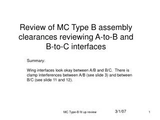
Comprehensive analysis of A-to-B and B-to-C interfaces, identifying clamp interferences and clearance measurements. Detailed examination of wing interfaces and winding forms. Recommendations for resolving interface issues.

E N D
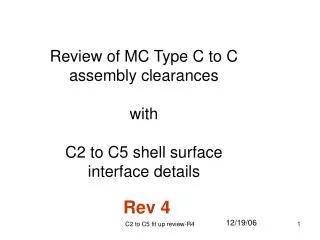
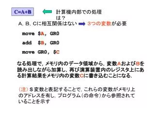
Review of MC Type B assembly clearances reviewing A-to-B and B-to-C interfaces Summary: Wing interfaces look okay between A/B and B/C. There is clamp interferences between A/B (see slide 3) and between B/C (see slide 11 and 12). 3/1/07 MC Type-B fit up review
Top Type-B Top Type-A B side Type-B A side Type-B to Type-A interface Bottom Bottom
Top A-to-B Fit-up 0.162” clearance Type-A Type-B Hole # 58 Type A Hole # 59 Type B See next slide for winding form interface. Hole # 60 Hole # 61 These clamps have an interference Clamps on A and B where there is interference or close contact is indicated. Clamp measured needed. Section Cut Looking Inboard
Type B Top Type A 0.374” This will be a tight region. Metrology data of the winding form and winding in this area would be useful.
Type-B Type-B wing A side Type-A wing pocket MC Type-A to Type-B large wing interface clearance is 0.378” at the edge in the CAD model.
Underside surface of Type-A shown in yellow. MC Type-A to Type-B large wing pocket interface clearance is 0.358” in the CAD model.
Type-A pocket surface Type-B, Side A MC Type-A to Type-B small wing pocket interface clearance is 0.445” in the CAD model.
Top Type-C Type-B Type-B to Type-C interface Cut-Away View Bottom
Outside Wing Flange B Side Interfacing Type-C surface MC Type-C to Type-B interface clearance at wing flange B side edge is 0.272” in the CAD model located at the edge of the wing. Only the edge indicated in the circle area needs to be measured. See next slide for further details.
There area should be ample space for the interfacing surface. MC Type-B to Type-C large wing interface surface clearance is 0.628” in the CAD model.
Type-B Type-C Rotated expanded view of area indicated. 0.247” shell clearance along this local region. This will be a tight region. It appears that the winding itself will fit okay (see next slide) although there is clamp problems
Hole # 63 Ignoring the clamps their appears to be no winding interferences. Hole # 65 Hole 61…I think! Type-C Clamp 61 and clamp hardware interferes with the Type-B winding and local cable.
MC Type-C to Type-B large wing pocket minimum interface clearance is 0.249” in the CAD model.
Measurements using the Leica laser tracker desired for flange surfaces.
Measurement needed along this local edge of the Type-B winding form. 0.50” clearance over most of this length. Type-B Side A
Measurement needed at the top of the Type-B in this region at the top of the MC. 0.72” Type A Type B