Download
1 / 22
400 likes | 1.58k Views
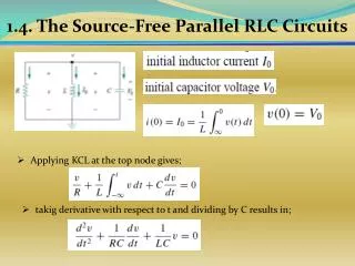
1. 4 . The Source-Free Parallel RLC Circuits. Applying KCL at the top node gives;. takig derivative with respect to t and dividing by C results in;. 1. 4 . The Source-Free Parallel RLC Circuits. s. 1. 4 . The Source-Free Parallel RLC Circuits. Overdamped Case (. negative and real .

E N D
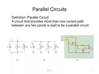
1.4. The Source-Free Parallel RLC Circuits • Applying KCL at the top node gives; • takig derivative with respect to t and dividing by C results in;
1.4. The Source-Free Parallel RLC Circuits Overdamped Case ( negative and real Critically Damped Case ( and
1.4. The Source-Free Parallel RLC Circuits Under Damped Case ( ;
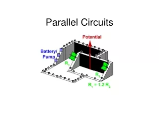
Example 1.5. In the parallel circuit of fig. , find for t>0, assuming Consider these cases; R=1.923 Ω, R=5 Ω, R=6.25 Ω. İf R=1.923 Ω
Example 1.5. Since ( in this case, overdamped. The roots of the characteristic equation are; Apply initial conditions to get and At t =0
Example 1.5. Must be differeantiated At t =0 With and the solution gets…
Example 1.5. When R=5 Ω Since α= , the responce is remains 10; Criticallydamped… Apply initial conditions to get and
Example 1.5. Must be differeantiated With and the solution gets…
Example 1.5. İn the last case R=6.25 Ω… Solution is… Response for three degrees of damping
1.5. Step Response of Series RLC Circuits This equation has two compenants; Natural response; Forcedresponse;
1.5. Step Response of Series RLC Circuits • İf we set contains only natural response ( • (t) can be expressedas three conditions; • The forced response is the steady-state or final value of • The final value of the capacitor voltage is the same as the source voltage.
1.5. Step Response of Series RLC Circuits • Thus the complate solution…
Example 1.6. For the circuit in Fig., find for t>0. Consider these cases: R=5Ω, R=4Ω,R=1Ω.
Example 1.6. • is the forced response or steady-state • response. • It is final value of the capacitor voltage. • =24 V. Take derivative of v(t) For t>0 , currenti,
Example 1.6. • Finally, • but we have to solve i(t)…
Example 1.7. Solution: • For t<0, the switch is open • The circuit partitioned into two independent subcircuits. Capacitor voltage equal the voltage of 20Ω resistor.
Example 1.7. • For t>0, the switch is closed • We have parallel RLC circuit. • The voltage source is off or short-circuited.
Example 1.7. The final value of I… Using initial conditions we get
Example 1.7. From i(t) we obtain v(t)…