Download
1 / 15
150 likes | 409 Views
Parallel Inductor-Resistor-Capacitor (RLC) Circuits. Session 4b for Basic Electricity A Fairfield University E-Course Powered by LearnLinc. Module: Basic Electronics (AC Circuits and Impedance: two parts).

E N D
Parallel Inductor-Resistor-Capacitor (RLC) Circuits Session 4b for Basic ElectricityA Fairfield University E-CoursePowered by LearnLinc Basic Electricity
Module: Basic Electronics(AC Circuits and Impedance: two parts) • Text: “Electricity One-Seven,” Harry Mileaf,Prentice-Hall, 1996, ISBN 0‑13‑889585‑6 (Covers much more material than this section) • References: • “Digital Mini Test: Principles of Electricity Lessons One and Two,” SNET Home Study Coordinator, (203) 771-5400 • Electronics Tutorial (Thanks to Alex Pounds) • Electronics Tutorial (Thanks to Mark Sokos) • Basic Math Tutorial (Thanks to George Mason University) • Vector Math Tutorial (Thanks to California Polytec atatom.physics.calpoly.edu ) • Alternating Current and Impedance • 5 on-line sessions plus one lab • Resonance and Filters • 5 on-line sessions plus one lab Basic Electricity
Section 4: AC, Inductors and Capacitors • 0BJECTIVES:This section discusses AC voltage / current and their effects on parallel circuit components (resistors, inductors, transformers and capacitors). The concept of resonance and its use to produce filters is also described. Basic Electricity
Section 4 Schedule: Session 4a – 07/08Session 4b – 07/10(break for a week)Session 4c – 07/22 Session 4d – 07/24(lab - 07/27, Sat.) Session 4e – 07/29 (Quiz 4 due 08/12)Session 4f – 08/12 08/14 08/17 Parallel L-C Circuits Parallel R-L-C Circuits(no class on 07/15 or 07/17)Parallel Resonance Tuning and Filters Transformers and Impedance MatchingReview (Discuss Quiz 4)MT2 ReviewMT2 – AC Circuits Text 4.114 – 4.122Text 4.123 – 4.132 Text 4.133 – 4.146 Text 4.147 – 4.151Text 4.152 – 4.160 Basic Electricity
Session 3 (Parallel L-C) Review • Capacitive reactance XC = 1/2fC at -90º • Inductive reactance XL = 2fL at 90º • Impedances in parallel add as inverses • Adding Vectors • Separately add their horizontal and vertical components • Graphically: head-to-tail or parallelogram • Here the vectors are in opposite directions; they just subtract. • Inductive reactance points up (90º) • Capacitive reactancepoints down (-90º) • Multiplying Vectors • Multiply their magnitudes (lengths) • Add their phases • Dividing Vectors • Divide their magnitudes (lengths) • Subtract their phases • Ohm’s and Kirchoff’s laws still work with AC Basic Electricity
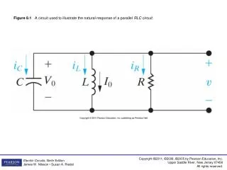
Parallel R-L-C Circuits • Voltage (ref. phase) is the same across all parallel components • Branch currents add (vectors) to produce ILine • Impedances in parallel add (vectors) as inverses Basic Electricity
A Two-Step Solution • Solve an RLC in two steps • Combine the L and C branches (both vertical) • Add the resistor branch to the result (as a vector) Basic Electricity
Parallel RLC- Current • AC currents always add as vectors • Voltage (ref. Phase) is the same across all parallel components • Inductor - IL points down (Lags voltage by 90º) • Capacitor - IC points up (Leads voltage by 90º) • Add IL and IC (they subtract) to get ILine • IL = 1-90º = -190º • IC = 290º • ILC = (2-1)90º = 190º (capacitive circuit) • Now add IR • |ILine| = (12 + 32)½ = 10½ = 3.162 • ILine = arctan(1/3) = 18.435° = 0.322 Radians Basic Electricity
Parallel LC- CurrentWaveforms • AC currents always add as vectors • Voltage (ref. Phase) is the same across all parallel components • Resistor current is in phase with the voltage • Inductor - IL points down (Lags voltage by 90º) • Capacitor - IC points up (Leads voltage by 90º) • Line current - ILine has a phase between ILC andIR Basic Electricity
Parallel RLC - Impedance • Impedances in parallel add as inverse vectors • XL (up) and XC (down) are in opposite directions • First combine the L and C branches • 1/XL = 1/(1090º )= 0.1-90º • 1/XC = 1/(5-90º )= 0.290º • 1/XLC = 0.190º • 1/R = 0.050º • |1/Z| = (0.052 + 0.12)½ = (0.0025 + 0.01)½ = (0.0125)½ = 0.1118 • 1/Z = arctan(0.1/0.05) = 63.4º • Z = 9-63.4º (capacitive) Basic Electricity
The Effect of Frequency • ZL = 2fL (rises linearly with frequency) • ZC = 1/2fL (decreases with frequency) • Resonance is when they are equal and cancel; the impedance is then just the resistance Basic Electricity
Example • First find the Branch currents • IC = 220/100 = 2.290º • IR = 220/500 = 0.440º • ILC = (2.2-1)90º = 1.2 90º • | ILine| = (0.442 + 1.22)½ = (0.1936 + 1.44)½ = (1.6336)½ = 1.278 amps • ILine = arctan(1.2/0.44) = arctan(2.72) = 69.9º Basic Electricity
Example (continued) • First find the Inductor reactance • XL = 220 volts/1 amp = 22090º Ohms • Now add the impedances as inverses • 1/XLC = 1/22090º + 1/100-90º = 0.004590º + 0.01-90º = 0.0055-90º • |1/ Xt| = (0.00552 + 0.0022)½ = (0.00003 + 0.000004)½ = (0.000034)½ = 0.0058 ( |Xt| = 172 ohms, Iline = 220/172 = 1.28 amps) • 1/ Xt = arctan(-0.0055/0.002) = arctan(-2.75) = -70º Basic Electricity
Resonance • XL and XC cancel • Parallel Resonance • High Impedance • Low line current (high current in the LC loop!) • Series Resonance • Low impedance • High line current • Resonant frequency2fL = 1/2fCf = 1/2(LC)½ Basic Electricity
Section 4 Schedule: Session 4a – 07/08Session 4b – 07/10(break for a week)Session 4c – 07/22 Session 4d – 07/24(lab - 07/27, Sat.) Session 4e – 07/29 (Quiz 4 due 08/12)Session 4f – 08/12 08/14 08/17 Parallel L-C Circuits Parallel L-R-C Circuits (no class on 07/15 or 07/17) Parallel ResonanceTuning and Filters Transformers and Impedance MatchingReview (Discuss Quiz 4)MT2 ReviewMT2 – AC Circuits Text 4.114 – 4.122Text 4.123 – 4.132Text 4.132 – 4.146Text 4.147 – 4.151Text 4.152 – 4.160 Basic Electricity