Download
1 / 37
400 likes | 827 Views
W12D2 RC, LR, and Undriven RLC Circuits; Experiment 4. Today ’ s Reading Course Notes: Sections 11.7-11.9, 11.10, 11.13.6; Expt. 4: Undriven RLC Circuits. Math Review Week 13 Tuesday 9pm-11 pm in 26-152 PS 9 due Week 13 Tuesday at 9 pm in boxes outside 32-082 or 26-152

E N D
W12D2RC, LR, andUndriven RLC Circuits;Experiment 4 Today’s Reading Course Notes: Sections 11.7-11.9, 11.10, 11.13.6; Expt. 4: Undriven RLC Circuits
Math Review Week 13 Tuesday 9pm-11 pm in 26-152 PS 9 due Week 13 Tuesday at 9 pm in boxes outside 32-082 or 26-152 Next Reading Assignment W12D3 Course Notes: Sections 11.8-9, 11.12-11.13 Announcements
Outline Experiment 4: Part 1 RC and LR Circuits Simple Harmonic Oscillator Undriven RLC Circuits Experiment 4: Part 2 Undriven RLC Circuits
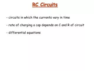
RC Circuit Charging Solution to this equation when switch is closed at t = 0:
RC Circuit: Discharging Solution to this equation when switch is closed at t = 0 time constant:
RL Circuit: Increasing Current Solution to this equation when switch is closed at t = 0: (units: seconds)
RL Circuit: Decreasing Current Solution to this equation when switch is opened at t = 0: (units: seconds)
Measuring Time Constant • Pick a point 1 with • Find point 2 such that • By definition then 2) In the lab you will plot semi-log and fit curve (make sure you exclude data at both ends)
DemonstrationMass on a Spring:Simple Harmonic MotionMass on a Spring (C 2) http://scripts.mit.edu/~tsg/www/demo.php?letnum=C%202&show=0
Mass on a Spring (2) (1) What is Motion? (4) (3) Simple Harmonic Motion x0: Amplitude of Motion f: Phase (time offset)
Simple Harmonic Motion Amplitude (x0)
Concept Question: Simple Harmonic Oscillator Which of the following functions x(t) has a second derivative which is proportional to the negative of the function 1. 2. 3. 4.
Concept Question Answer: Simple Harmonic Oscillator Answer 4. By direct calculation, when
Mass on a Spring: Energy (1) Spring (2) Mass (4) Mass (3) Spring Energy has 2 parts: (Mass) Kinetic and (Spring) Potential Energy sloshes back and forth
LC Circuit • Set up the circuit above with capacitor, inductor, resistor, and battery. • Let the capacitor become fully charged. • Throw the switch from a to b. • What happens?
LC Circuit It undergoes simple harmonic motion, just like a mass on a spring, with trade-off between charge on capacitor (Spring) and current in inductor (Mass). Equivalently: trade-off between energy stored in electric field and energy stored in magnetic field.
Energy stored in electric field Energy stored in magnetic field Energy stored in electric field Energy stored in magnetic field
Concept Question: LC Circuit Consider the LC circuit at right. At the time shown the current has its maximum value. At this time: • the charge on the capacitor has its maximum value. • the magnetic field is zero. • the electric field has its maximum value. • the charge on the capacitor is zero.
Concept Q. Answer: LC Circuit Answer: 4. The current is maximum when the charge on the capacitor is zero Current and charge are exactly 90 degrees out of phase in an ideal LC circuit (no resistance), so when the current is maximum the charge must be identically zero.
LC Circuit: Simple Harmonic Oscillator Simple harmonic oscillator: Charge: Angular frequency: Amplitude of charge oscillation: Phase (time offset):
LC Oscillations: Energy Notice relative phases Total energy is conserved !!
RLC Circuit: Energy Changes Include finite resistance: Multiply by Decrease in stored energy is equal to Joule heating in resistor
Damped LC Oscillations Resistor dissipates energy and system rings down over time. Also, frequency decreases:
Appendix: Experiment 4: Part 2Undriven RLC CircuitsGroup Problemand Concept Questions
Problem: LC Circuit Consider the circuit shown in the figure. Suppose the switch that has been connected to point a for a long time is suddenly thrown to b at t = 0. Find the following quantities: (a) the frequency of oscillation of the circuit. (b) the maximum charge that appears on the capacitor. (c) the maximum current in the inductor. (d) the total energy the circuit possesses as a function of time t.
Concept Question: Expt. 4 In today’s lab the battery turns on and off. Which circuit diagram is most representative of our circuit? • 1 • 2 • 3 • 4 1. 2. 3. 4. Load lab while waiting…
Concept Question Answer: Expt. 4 1. Answer: There is resistance in the circuit (in our non-ideal inductor). The battery switching off doesn’t break the circuit but allows it to ring down
Concept Question: LC Circuit The plot shows the charge on a capacitor (black curve) and the current through it (red curve) after you turn off the power supply. If you put a core into the inductor what will happen to the time TLag? • It will increase • It will decrease • It will stay the same • I don’t know
Concept Question Answer: LC Circuit • Answer 1. • TLag will increase. Putting in a core increases the inductor’s inductance and hence decreases the natural frequency of the circuit. Lower frequency means longer period. The phase will remain at 90º (a quarter period) so TLag will increase.
Concept Question: LC Circuit If you increase the resistance in the circuit what will happen to rate of decay of the pictured amplitudes? • It will increase (decay more rapidly) • It will decrease (decay less rapidly) • It will stay the same • I don’t know
Concept Question Answer: LC Circuit Answer: 1. It will increase (decay more rapidly) Resistance is what dissipates power in the circuit and causes the amplitude of oscillations to decrease. Increasing the resistance makes the energy (and hence amplitude) decay more rapidly.