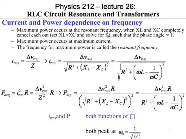
Source-Free RLC Circuit
150 likes | 427 Views
Source-Free RLC Circuit. Parallel RLC Network. Objective of Lecture. Derive the equations that relate the voltages across a resistor, an inductor, and a capacitor in parallel as: the unit step function associated with voltage or current source changes from 1 to 0 or

Source-Free RLC Circuit
E N D
Presentation Transcript
Source-Free RLC Circuit Parallel RLC Network
Objective of Lecture • Derive the equations that relate the voltages across a resistor, an inductor, and a capacitor in parallel as: • the unit step function associated with voltage or current source changes from 1 to 0 or • a switch disconnects a voltage or current source into the circuit. • Describe the solution to the 2nd order equations when the condition is: • Overdamped • Critically Damped • Underdamped
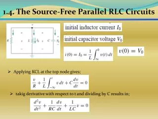
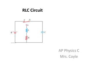
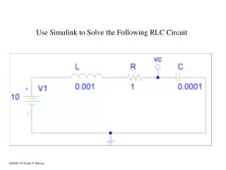
RLC Network • A parallel RLC network where the current source is switched out of the circuit at t = to.
Boundary Conditions • You must determine the initial condition of the inductor and capacitor at t < toand then find the final conditions at t = ∞s. • Since the voltage source has a magnitude of 0V at t < to • iL(to-) = Isand v(to-) = vC(to-) = 0V • vL(to-) = 0V and iC(to-) = 0A • Once the steady state is reached after the voltage source has a magnitude of Vs at t > to, replace the capacitor with an open circuit and the inductor with a short circuit. • iL(∞s) = 0A and v(∞s) = vC(∞s) = 0V • vL(∞s) = 0V and iC(∞s) = 0A
Selection of Parameter • Initial Conditions • iL(to-) = Is and v(to-) = vC(to-) = 0V • vL(to-) = 0V and iC(to-) = 0A • Final Conditions • iL(∞s) = 0A and v(∞s) = vC(∞s) = oV • vL(∞s) = 0V and iC(∞s) = 0A • Since the current through the inductor is the only parameter that has a non-zero boundary condition, the first set of solutions will be for iL(t).
Note that the equation for the natural frequency of the RLC circuit is the same whether the components are in series or in parallel.
Overdamped Case • a > wo • implies that L > 4R2C s1 and s2 are negative and real numbers
Critically Damped Case • a = wo • implies that L = 4R2C s1 = s2 = - a = -1/2RC
Underdamped Case • a < wo • implies that L < 4R2C
Other Voltages and Currents • Once current through the inductor is known:
Summary • The set of solutions when t > to for the current through the inductor in a RLC network in parallel was obtained. • Selection of equations is determine by comparing the natural frequency woto a. • Coefficients are found by evaluating the equation and its first derivation at t = to- and t = ∞s. • The current through the inductor is equal to the initial condition when t < to • Using the relationships between current and voltage, the voltage across the inductor and the voltages and currents for the capacitor and resistor can be calculated.