Download
1 / 47
480 likes | 639 Views
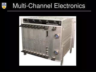
Problems and Solutions in high-rate multi-channel Hybrid Photodiode design HPD’s for the CMS Hadronic Calorimeter Professor Priscilla Cushman University of Minnesota. The US-CMS HCAL Collaboration

E N D
Problems and Solutions in high-rate multi-channel Hybrid Photodiode design HPD’s for the CMS Hadronic Calorimeter Professor Priscilla CushmanUniversity of Minnesota The US-CMS HCAL Collaboration Fermilab Florida State Purdue Notre Dame University of Illinois (Chicago) University of Mississippi University of Maryland Rochester University of Minnesota Professor Priscilla CushmanUniversity of Minnesota
The CMS Tile/Fiber Hadronic Calorimeter HCAL Professor Priscilla CushmanUniversity of Minnesota
Reading out the Towers of Tiles with WLS fiber and HPD’s Professor Priscilla CushmanUniversity of Minnesota
Optical Decoder Unit HPD mount aligned to cookie and plate Optical decoding from layer into tower bundles occurs at the readout boxes. Fiber Optic Cables attach to a patch panel Professor Priscilla CushmanUniversity of Minnesota
Stringent Photodetector Requirements • Magnetic Field of 4 Tesla • Linear Response from MIP to 3 TeV Shower • DC Calibration to 2% using Radioactive Source • Integrated Neutron Dose of up to 5 x 10¹⁰ n/cm2 • Integrated Output Charge up to 3 Coulombs • Use same system in HO for ease of integration • Outer Barrel and Endcap have relaxed constraints • tag muons (10 p.e./MIP) and measure shower tails • many channels => low cost • fringe field Professor Priscilla CushmanUniversity of Minnesota
CMS diode design 19 x 5.4mm 73 x 2.68mm The Hybrid Photodiode Tube Fabrication byDelft Electronic Products (Netherlands)Subcontracts:Canberra (Belgium) diodesSchott Glass (USA) fiber optic windows Kyocera (Japan) vacuum feedthru/ceramic carrier • 12 kV across 3.3 mm gap with Vth < 3 kV => Gain of 2500 • Silicon PIN diode array, T-type. Operated at 80 V reverse bias • Thin (200 mm) with 100 V reverse bias for fast charge (holes) collection • Aluminized surface and AR Coating Professor Priscilla CushmanUniversity of Minnesota
How They Work Photocathode Fiber-Optic Window Electrons from the photocathode are accelerated in a high electric field and stop in the diode where they generate electron hole pairs. Detect current as holes move across the depletion region in the back-illuminated version. e Ceramic feedthrough PIN Diode array Gain 4000 0 0 8 16 kV 4 Professor Priscilla CushmanUniversity of Minnesota
Anatomy of a Decision APD vs HPD decision (1995-6 CERN test beams)System Integration Issues NIM A387 (1997) 107 Signal/Noise at low light-levels AC:1 MIP=7-10 peDC:Radioactive Source Validation B-field Studies at 4-5 T NIM A418 (1998) 300 Radiation Damage at Oak Ridge NIM A411 (1998) 304 Extensive Bench Studies Project Approval and CMS-specific design Negotiate specifications and price Acquire prototypes and test NIM A442 (2000) 289 Iterate From Validation to Quality Assurance and YieldThis has been LONGER than we expected ! Professor Priscilla CushmanUniversity of Minnesota
Magnetic Field Issues Performance measured at 4 TeslaDoesn’t break Image shift = gap * tanqSmall gain shifts (angular effects and backscattter) Align tube axis parallel to fieldField locally uniform: ~ 5o (6o) inclination in HB (HE) Minimum gap (eases tolerance) vs HV (maintain gain) Maintain sufficient space between fiber bundlesMechanically robust cookies Maximize photocathode active area Pixel position must be measured (and aligned) to 50 mm Professor Priscilla CushmanUniversity of Minnesota
Electronics Interface Board HV Cable HPD Cookie RBX RBX FIBERS This has been a development project (the tube) Larger active area: Less room for HV connection, possible field distortions Minimize gap: Improve tube components HV coax cable : Reliability and compatibility with RBX RBX mountings and cookies must be rubber insulated Gold-plated pins: Enables us to use ZIF sockets - questions of gold diffusion Professor Priscilla CushmanUniversity of Minnesota
After silicon rubber potting, at 15 kV Time (hrs) nAmps HV Discharge to HPD Mounting Current across mount at 12 kVwith normal RBX configuration Time (hrs) nAmps Lifetime Setup modified for HV Monitor Trigger: 1 nA for spikes + 1.5 minute interval Professor Priscilla CushmanUniversity of Minnesota
Photocathode has a typical e-f/kTdependence on Temperature Keep red sensitivity low. Fitted f eff ranged from 1 - 1.33Dark counts at 25oC are 50 Hz – 1 kHz Richardson-Dushman Equation Jth = AoT2exp(-eff/kT) eff = 1.09 for this fit. Temperature (oC) Professor Priscilla CushmanUniversity of Minnesota
AR (16 nm sputtered Si)Metal (25 nm AL)Barrier (25 nm SiO2) n++ contact n+ bulk (200 mm thick) n++ p+ p+ p+ p+ p+ n++ This has been a development project ( the diode) Custom Pixel Design: 19 ch (towers) and 73 ch (short stacks) Higher pin-out density: wire-bonds =>glass feedthrus => ceramic from Kyocera Alignment to 50 mm: manufacturer tolerances tightened, new measurement procedures Improved rise time: Thinner silicon: 200 mm replaces 300 mm Guard ring and drain structure: lower leakage current and better uniformity for edge pixels Lower depletion voltage and better control of process: higher breakdown voltage Surface aluminization and edge traces: Reduce negative crosstalk: 300 W /sq => 1.7 W /sq Anti-reflective coating: Reduce positive crosstalk from reflected light 2 side-contacts (100 nm thick Al) Bump-bonded vacuum feedthru Professor Priscilla CushmanUniversity of Minnesota
Capacitance as a function of reverse bias voltage C73 = 5 pF/pixelC19 = 20 pF/pixel C(interface card and leads) = 13 pF Depletion at 43 V and 25 V 33 pF 18 pF Professor Priscilla CushmanUniversity of Minnesota
Internal Electric Field in the bulk n-type siliconOutput current and pulse width can be calculated with this simple model E E(d) = 2Vd + E(0) = Vb+Vd d d E(0) =Vb-Vdd x=0 x=d x n++ h n+ p+ h h pe’s V=0 V=Vb h h from t = 0 to t = D Professor Priscilla CushmanUniversity of Minnesota
Drift time of holes translates into pulse width DSimple form for over-depletion matches data Pulse Width From fit: Consistency check: Hole mobility in silicon is m = 450 cm2/Vs Professor Priscilla CushmanUniversity of Minnesota
Pulse width can be shortened by reducing wafer thickness d or by increasing bias voltage, Vb Drift time is approximately given by and the shape of the plateau mirrors the internal electric field 300 mm thick 200 mm thick Professor Priscilla CushmanUniversity of Minnesota
For higher depletion (lower ohmic silicon) Vb-Vd ~ Vb is not true Fit data to modelearly (5 kW-cm silicon) diodes 12 kW-cm diodes We now SPECIFY > 8 kW-cm 50 ns 40 ns 30 ns 20 ns 10 ns 0 Pulse Width D Operating bias voltage = 80 V 1/Vb 200 100 66 50 40 33 28.5 25 Volts Bias Voltage Professor Priscilla CushmanUniversity of Minnesota
No evidence of breakdown, even at 500 volts! Professor Priscilla CushmanUniversity of Minnesota
Reminder: on the same scale Flatter plateau and higher breakdown for new diodes R0003241 (200 micron, 73-channel new-style diode) Pulse Width in nsec Professor Priscilla CushmanUniversity of Minnesota
Positive crossstalk now observed ! AC Crosstalk eliminated by Aluminization 33 34 35 36 37 Pixels in center row Professor Priscilla CushmanUniversity of Minnesota
Backscatter crosstalk for a 19-channel Aluminized HPD Convolution of hexagonal pixel shape with backscatter radial distribution Read outnearest neighbor Move fiber d Professor Priscilla CushmanUniversity of Minnesota
Ballistic model of Backscattering. 10 keV electrons 7654321 Radial Distance from impact point (mm) 0o 45o 90oInitial scattering angle of backscattered electron Professor Priscilla CushmanUniversity of Minnesota
Trajectories of Backscattered Electrons B = 0 Tq = 45o B = 0.15 Tq = 45o Radial distance B = 4 Tq = 75o Radial distance is a minimum here Professor Priscilla CushmanUniversity of Minnesota
Number of backscattered e’s as a function of radial distance from impact point B = 0 T B = 0.15 T 0 1 2 3 4 5 6 7 mm 0 0.5 1 1.5 2 2.5 3 3.5 4 mm B = 0.2 T B = 4 T 0 0.5 1 1.5 2 2.5 3 mm 0 .025 .05 .075 .1 .125 .15 mm Professor Priscilla CushmanUniversity of Minnesota
73-ch tubeTotalDC Crosstalk(2.7 mm pixels)B=0 B=1.5 T Bare silicon18% 7%Aluminized 29% 16%Al with AR 12.4% 4.3% STILL some positive crosstalkand Al is worse than silicon Pixel number 1-2 33-41 72-73 Positive crosstalk from backscatter can be removed by B-field Professor Priscilla CushmanUniversity of Minnesota
Test Confirms Reflected Light Light injected thru fiber APD views reflected light FIBER OPTIC & PHOTOCATHODE Light Re-emitted photoelectrons photoelectrons pe backscatter focussed by B DIODE ARRAY Professor Priscilla CushmanUniversity of Minnesota
Compare residual HPD crosstalk in B-Fieldwith APD measurement of optical reflection Professor Priscilla CushmanUniversity of Minnesota
Some Options 10 nm Ag120 nm SiO2 Ag oxidizes quickly Au not available 8 nm A-Si15 nm Ag50 nm SiO2 16 nm A-Si25 nm Al25 nm SiO2 DEP makes samples on old diodes using sputtering Study Problem at Minnesota, then export technology to DEP Model IMD - optical modeling package for multilayer structures(by David L. Windt, http://cletus.phys.columbia.edu/windt/idl) monochrometer Data Samples: glass slides with various coatings (PECVD) PIN diode Professor Priscilla CushmanUniversity of Minnesota
Comparison of Model vs Data calibrates PE-CVD Processa-Si:H (SiH4 gas) deposited on glass slides 5.4 min10.8 nm 20 min52.1 nm 30 min76.7 nm 60 min153.5 nm Professor Priscilla CushmanUniversity of Minnesota
Glass slides + 25 nm Al + 14 nm a-Si:H Professor Priscilla CushmanUniversity of Minnesota
First DEP attempt at 16 nm a-Si Minnesota test slides 14 nm a-SiH 25 nm Al 25 nm SiO2 MC for 10 nm We tell them to add another 6 nm Angular Dependenceof test slides MC for 16 nm Reflectance Studies Professor Priscilla CushmanUniversity of Minnesota
Specifications are finalized in ContractQuality Assurance protocol detailed Professor Priscilla CushmanUniversity of Minnesota
Specifications are finalized in Contract...continued Professor Priscilla CushmanUniversity of Minnesota
Quality Assurance Bake-out at 13 kV for 2 weeks DC Station Machine custom ring Alignment measurements for 50 micron tolerance Leakage current for each pixel and guard ring @ 80V 2-D response scans (10kV, 80 V) HV gain, reverse bias curve crosstalk checks alignment AC Station Lifetime: Q, Cf252, HV pe spectra, AC xtalk capacitance vs bias subset High Rate and B-Field tests To FNAL for installation in readout boxes Evaluate 500 tubes, automated procedure, complete web-accessible database fail pass Return to DEP Professor Priscilla CushmanUniversity of Minnesota
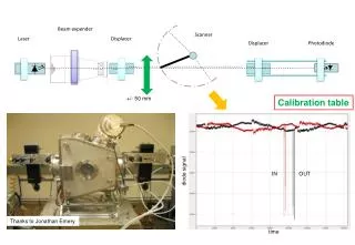
Precision Registration Metal alignment plate Integratingsphere Focussing optics Stabilized light source Mount HPD Green filter Scanning Table • Test fixture = Standard Mount + metal plate with 3 alignment holes • Scan to find centroid of alignment holes • Same scan finds pixel intersections above and below metal piece by iterative sector equalization • Machine shop uses measured Dx, Dy, q to produce Custom Ring Professor Priscilla CushmanUniversity of Minnesota
Precision Registration (in assembly) • Each ring is registered to its HPD via alignment pins • Plate and Cookies are universal Electronics Interface Board Ring HV Cable HPD Plate Plate Cookie FIBERS Alignment Pins Optical Decoding Unit Professor Priscilla CushmanUniversity of Minnesota
Universal Cookie + Plate 73-channel (HB) 19-channel (HB right) Professor Priscilla CushmanUniversity of Minnesota
HPD alignment after correction for 8 tubes Professor Priscilla CushmanUniversity of Minnesota
Samples from DC database Pixel Number Dark Current 1 8.6827e-0092 9.2811e-0093 2.4709e-0084 8.6967e-0095 8.995e-0096 2.2894e-0087 8.2391e-0098 2.1001e-0089 9.1783e-00910 2.2305e-008 11 1.36793e-00812 8.7693e-00913 2.0977e-00814 3.0818e-00815 1.78352e-00816 7.1035e-00917 7.2061e-00918 8.2694e-00919 7.2356e-009 Total Current 2.6605e-007 Professor Priscilla CushmanUniversity of Minnesota
AC Station: Viking chip serial readout at 10 MHz AC-Coupling 2 chip 128 channel PA Repeater card Laptop with ADC card HPD + interface card 128 Multiplexer Sample& hold Shaper 10 MHz readout Professor Priscilla CushmanUniversity of Minnesota
Individual spectra for each pixel from AC Station19-channel tube at low light levels Professor Priscilla CushmanUniversity of Minnesota
Blue LED’s PIN reference diodes HPD Pixel 1 1.0 mm diam. WLS fibers Pixel 2 Lifetime Issues Lifetime Monitoring Stations monitor current (PIN diodes, HPD) and temperature Radiation Damage: (10 CMS years = 5 x 10¹⁰ n/cm2 in worst region) Expose samples to Cf252 Oak Ridge: Early HPD version to 1013 n/cm2 in 1997 tests. Minnesota: Low flux drawer instrumented Aluminized new HPD to >1011 n/cm2 in 2001 Integrated Charge: (10 CMS years = 3 C over 25.6 mm2 pixel at high h) Expose to accelerated rate plus control pixel at CMS rate. Surface scans done before and after exposure distinguish between photocathode degradation and silicon damage. Professor Priscilla CushmanUniversity of Minnesota
Concentrated light in a small fiber will damage photocathodeThis is far beyond the CMS rate which allows for photocathode self-annealing Green light with HV = 8 kV Scans total tube response Red light with HV=0 Scans only silicon Professor Priscilla CushmanUniversity of Minnesota
Accelerated aging tests: Red (upper curves) = 73-ch aluminized HPD Blue (lower curves) = old tube with poor potting All curves normalized to reference diode and corrected for temperature shifts 6 CMS months for high h towerat expected CMS rate 6 CMS years for high h towerat 13 x expected rate Lifetime setup traps sparking by triggering on current spikes from High Voltage Supply Professor Priscilla CushmanUniversity of Minnesota
Irradiate 73-channel aluminized HPD - leakage current increases Flux = 7 x 10⁹ n/(cm2 hr)MeV neutrons from Cf252 Integrated dose is geometrically equivalent to 4.5 x 10¹¹ n/cm2 head on HPD (light-dark) PIN diode => Injected light is constant Leakage current rising at 46 pA/hr hours 10 CMS years Day 1 Day 2 Day 3 Day 4 Professor Priscilla CushmanUniversity of Minnesota
Conclusions 5 years ago, no existing technology could satisfy our specifications. Development project was initiated with one Company - DEPwith backup plans which included Hamamatsu and Litton Rigorous evaluation must include accelerated aging and test beamsand enough prototype detectors to understand the yield. The anticipated problems are not the ones that really bite you. This takes time!In the last year, the HPD subsystem has approached “critical path” in the CMS Project. Final Result: CMS HCAL gets what it needs (so we can find the Higgs) and a better product is offered to the general public. Professor Priscilla CushmanUniversity of Minnesota