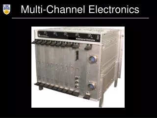
Multi-Channel Electronics
Multi-Channel Electronics. SCUBA2 MCE. 4 readout cards (RC) each reads 8 output columns through 14-bit 50MHz ADCs 1 address card (AC)= SQ1_bias addresses the [41] rows at add ≤ 850kHz, set by L/R frame ≤ add /41≈ 20kHz 1 clock card (CC)

Multi-Channel Electronics
E N D
Presentation Transcript
SCUBA2 MCE • 4 readout cards (RC) • each reads 8 output columns through 14-bit 50MHz ADCs • 1 address card (AC)= SQ1_bias • addresses the [41] rows at add≤ 850kHz, set by L/R • frame≤add /41≈ 20kHz • 1 clock card (CC) • master card: interprets commands and synchronizes all the cards. Drives fibre to PC. • 3 bias cards (BC) • BC 1: Squid Series Array Feedback (x32) + TES bias(x1) • BC 2: Squid 2 feedback (x32) • BC 3: SQ2 bias(x32) + TES heaters(x1)
SPIDER MCE • SPIDER (as well as SPUD and BICEPII) have up to 33 rows and 16 columns for each array • Repackaged MCE: • 2 RC’s • Reorganized BC’s duties • Additional features: • More DET_BIAS (already in place) • SQ2_fb fast switching (to achieve a better lock and to remove summing coil pickup switching off all SQ1_bias and adjusting SQ2_fb. However with fixed values. Or we could effectively connect the dark SQ sq1_fb with the sq2_fb)
Cards in SPIDER MCE • 3 BC’s • BC1 0/16 SSA_fb, 0/16 SQ2_BIAS, DET_BIAS_ORG • BC2 0/16 (possibly fast switching) SQ2_FB • BC3 0/16 DET_BIAS • In the current configuration slow SQ2_FB and 16 DET_BIAS slightly different from DET_BIAS_ORG • 2 RC’s • RC1 0/7 SQ1_FB, 0/7 SSA_BIAS • RC2 8/15 SQ1_FB, 8/15 SSA_BIAS • 1 AC, 1 CC
Subrack in SPIDER MCE T Felton design
Backplane in SPIDER MCE SQ1_fb: it was 450A, now 150 A because of the increase in the mutual inductance of MUX06. Is it fine? DET_BIAS: the maximum we can achieve now is 4mA. It can be increased. Should it?
PSU in SPIDER MCE • Power supply: • We currently use an ACDCU with a switching power supply • For SPIDER: • we may use batteries • 119W for SCUBA2. For SPIDER: 16 columns 73W (23W each RC)
Cooling SPIDER MCE to the gondola frame, used as heatsink • Cooling: • We currently • use fans and • filtered air with positive pressure • SPIDER MCE will be radiatively cooled using circulating • fluid with a pump T Felton design
SEU in SPIDER MCE • Cosmic rays on FPGA and SEU tolerance: 1 per month at JCMT ~1 SEU / board / LDB flight. We are already in contact with the TRIUMF particle accelerator for realistic neutron fluency test (in fact, test flight would not reveal the real effect). • Altera Stratix III FPGA’s offer additional on chip monitoring and testing features wrt Stratix I. We would not use it for the test flight. Maybe for SPIDER. • PC’s in pressure vessel (HD). Two with crosscomunication. • The syncbox could be there as well.
Schedule for SPIDER MCE • For the new repackaged MCE with no cards redesign: • Finalize the design 1-2 weeks • Backplane 6-8 weeks • Chassis our machine shop, 6 weeks • New FPGA? Probably not for the test flight. Maybe for SPIDER • Cooling system 4-5 weeks • New filter box and flex (rigid-flex, 1 connector less, and no ground plane) 6-8 weeks • Test 6-8 weeks • SEU test ? • New boards new year
Modulation schemes • TES bias • SQ1 bias • SQ1 fb (switching) • SQ1 fb (ramping)
TES bias • The TES bias could be square (or sine) wave modulated at ~1kHz. We have the firmware for s.w. that can run as fast as half the framerate • However, if the bias crosses zero for more than few hundreds s, than the TES’ may not recover Superconducting branch Normal branch Superconducting transition Acquired on the ACT CCam camera
TES bias • In any TES bias modulation scheme we need a firmware that has to run two separate servo loops. Synchronization is needed. Major firmware change for the read-out and the demodulation. • It can be tested in software since we can already acquire fast data at 2.2kHz (33 rows, 32GB/h), 26kHz (1row). We’d need bolometers to do tests. Acquired on the ACT MBAC camera
TES bias • In any TES bias modulation scheme we need a firmware that has to run two separate servo loops. Synchronization is needed. Major firmware change for the read-out and the demodulation. • It can be tested in software since we can already acquire fast data at 2.2kHz (33 rows, 32GB/h), 26kHz (1row). We’d need bolometers to do tests.
SQ1 bias modulation • We visit the SQ1 at up to 20kHz with RS on bias. We could select 2 different on bias’ and switch at sub-harmonics of 20kHz. • The firmware demodulation (i.e. remove off from on) would be straightforward since it would be a modification of the coadding we already implement. Acquired on the ACT CCam camera
SQ1 bias modulation • We visit the SQ1 at up to 20kHz with RS on bias. We could select 2 different on bias’ and switch at sub-harmonics of 20kHz. • We could invert the polarity of the SQ1_bias (although now it is not bipolar) and keep the same inverted polarity lock point. Acquired on the ACT CCam camera
SQ1 fb modulation (switch) • The SQ1_fb could be switched so that the PID feedback loop works in opposite SQ1 slope • A firmware should be created that enables opposite locking. That could be done with I-term=I·(-1)#frames except that it would take time • However it should require a fine tuning and • … Acquired on the ACT CCam camera
SQ1 fb modulation (switch) • The SQ1_fb could be switched so that the PID feedback loop works in opposite SQ1 slope • A firmware should be created that enables opposite locking. That could be done with I-term=I·(-1)#frames except that it would take time to relock • However it should require a fine tuning and • any asymmetry of the SQ1 V-phi doesn’t help Acquired on the ACT MBAC camera
SQ1 fb modulation (switch) • The SQ1_fb could be switched so that the PID feedback loop works in opposite SQ1 slope • A firmware should be created that enables opposite locking. That could be done with I-term=I·(-1)#frames except that it would take time to relock • However it should require a fine tuning and • any asymmetry of the SQ1 V-phi doesn’t help a combination of SQ1_bias and SQ1_fb modulation so that there are 4 different locking points and/or we keep the same lock point as K.Irwing suggested.
SQ1 fb modulation (ramp) • We throw away the PID feedback loop and we continuously ramp the SQ1_fb. This creates an effective modulation of the signal coming form the SQ1 V-phi curves • We already have a data mode that ramps the SQ1 fb. In the 14bits DAC each step can be as high as 10kHz • We look forward to test in software on a system with TES Acquired on the ACT CCam camera