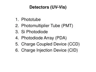

PHOTODIODE
E N D
Presentation Transcript
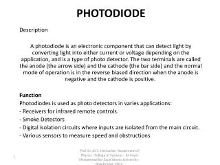
PHOTODIODE Description A photodiode is an electronic component that can detect light by converting light into either current or voltage depending on the application, and is a type of photo detector. The two terminals are called the anode (the arrow side) and the cathode (the bar side) and the normal mode of operation is in the reverse biased direction when the anode is negative and the cathode is positive. Function Photodiodes is used as photo detectors in varies applications: - Receivers for infrared remote controls. - Smoke Detectors - Digital isolation circuits where inputs are isolated from the main circuit. - Various sensors to measure speed and obstructions. Prof. Dr. Ali S. Hennache- Department of Physics - College of Sciences - Al-Imam Muhammad Ibn Saud Islamic University - Riyadh Sept. 2012.
PHOTODIODE • The photodiode is a p-n junction under reverse bias. • - Exposing a semiconductor to light can generate electron-hole pairs, which increases the number of free carriers and its conductivity. • - Only those that have correct wavelength can be absorbed by the semiconductor. • - Separation of charge can be collected and measured as current or voltage. • - If device is left open circuit voltage detected photovoltaic effect • - If device is short-circuited (or under reverse bias) photoconductive mode Prof. Dr. Ali S. Hennache- Department of Physics - College of Sciences - Al-Imam Muhammad Ibn Saud Islamic University - Riyadh Sept. 2012.
Prof. Dr. Ali S. Hennache- Department of Physics - College of Sciences - Al-Imam Muhammad Ibn Saud Islamic University - Riyadh Sept. 2012.
PHOTODIODE SYMBOL • The photodiode symbol shows the basic format for a diode. However the photodiode symbol also shows the light in the form of arrows striking the diode junction - the arrows are in the opposite direct to that of a light emitting diode where they emanate from the device. • There are several forms of photodiode that are available. Each type of photodiode has its own advantages and disadvantages, thereby allowing a choice of photodiode technology to be made to gain the best results. Factors including noise, reverse bias constraints, gain, wavelength, and more all play a part. With PIN, PN, avalanche and Schottky photodiodes all available, an informed choice can be made to ensure the optimum photodiode technology is used. Prof. Dr. Ali S. Hennache- Department of Physics - College of Sciences - Al-Imam Muhammad Ibn Saud Islamic University - Riyadh Sept. 2012.
PHOTO DETECTORS • - When a photon/light strikes a semiconductor, it can promote an electron from the valence band to the conduction band creating an electron-hole (e-h) pair. • - The concentration of these e-h pairs is dependent on the amount of light striking the semiconductor, making the semiconductor suitable as an optical detector. • There are two ways to monitor the concentration of e-h pairs: • 1- In photodiodes, a voltage bias is present and the concentration of light-induced e-h pairs determines the current through semiconductor. • 2- Photovoltaic detectors contain a p-n junction, that causes the e-h pairs to separate to produce a voltage that can be measured. Prof. Dr. Ali S. Hennache- Department of Physics - College of Sciences - Al-Imam Muhammad Ibn Saud Islamic University - Riyadh Sept. 2012.
PHOTODIODE RESPONSE TIME • The response time of a photodiode is defined as the time it takes for light generated carriers within the body of the diode to arrive at and cross the P-N junction. • When the diode is illuminated, photons of light penetrate into the silicon and are absorbed generating electron-hole pairs. The average depth of penetration of a photon is wavelength dependent. The penetration depth has a statistical distribution so that there will be some electron-hole pairs generated at all depths. • For light of very short wavelengths (ie UV and blue), most of the carriers will be generated very near the top surface of the diode. At this surface, due to the • termination of the crystal lattice, the minority carrier lifetime is extremely short and most of the carriers will recombine before they can cross the P-N junction and contribute to the photocurrent. • Light of longer wavelengths tends to penetrate deeper, generating a good number of carriers in the depletion region. The strong electric field that resides there sweeps the carriers across the junction at which point they contribute to the photocurrent. Prof. Dr. Ali S. Hennache- Department of Physics - College of Sciences - Al-Imam Muhammad Ibn Saud Islamic University - Riyadh Sept. 2012.
RISETIME OF A PHOTODIODE • Light of even longer wavelengths (ie IR) penetrates even deeper generating carriers in the area below the depletion region. As these carriers slowly diffuse towards the P-N junction, a fair number will recombine and never contribute to the photocurrent. • The risetime of a photodiode consists of three components: • 1. TCC (charge collection time) is the time required for the electric field, residing at the P-N junction, to sweep out carriers generated within or entering the depletion region. Typically TCC is less that 1 nsec. • 2. TRC (rise time associated with the RC time constant) is the time required to charge or discharge the photodiode's junction capacitance (CJ) through the external load resistance(RL) and is given as: TRC = 2.2 RL CJ Prof. Dr. Ali S. Hennache- Department of Physics - College of Sciences - Al-Imam Muhammad Ibn Saud Islamic University - Riyadh Sept. 2012.
RISETIME • In practice the RL term consists of the series combination of the external load resistance and internal series resistance of the photodiode (RS). The CJ term should include not only the junction capacitance of the photodiode but also all external capacitance such as the packaging capacitance and the external wiring capacitance. The series resistance of the photodiode (RS) is comprised of the resistance of the undepleted region of the diode and the contact resistance. RS is usually of the order of 10 ohms but can be up to a few hundred ohms in small area diodes of high resistivity silicon. When the output current of the photodiode is fed into a transimpedance op-amp the effective load resistance is the feedback resistance (RF) divided by the open loop gain. • 3.TDIF (diffusion time) is the time needed for carriers generated outside the depletion region to diffuse into the depletion region. The total risetime of a photodiode is equal to the square root of the sum of the squares of the three risetime components. Prof. Dr. Ali S. Hennache- Department of Physics - College of Sciences - Al-Imam Muhammad Ibn Saud Islamic University - Riyadh Sept. 2012.
TR is essentially equal to the largest of the three risetime components. Prof. Dr. Ali S. Hennache- Department of Physics - College of Sciences - Al-Imam Muhammad Ibn Saud Islamic University - Riyadh Sept. 2012.
LIGHT EMITTING DIODES (LEDS) • A light emitting diode is an electronic component and semiconductor light source. The two terminals are called the anode (the arrow side) and the cathode (the bar side). • An LED has the property to create light when current pass in one direction from the anode to the cathode but it blocks current flowing in the other direction from the cathode to the anode and no light is created in this direction. The arrow in the symbol points in the opposite direction as electron flow because it was based on conventional current flow before the discovery of electrons. In other words current will flow through the LED if the anode (arrow side) is positive and the cathode (bar side) is negative. • LED’s are available in various colours including the visible, ultraviolet and infrared wavelengths. Prof. Dr. Ali S. Hennache- Department of Physics - College of Sciences - Al-Imam Muhammad Ibn Saud Islamic University - Riyadh Sept. 2012.
A Light Emitting Diode (LED) on the left and the symbol on the right Prof. Dr. Ali S. Hennache- Department of Physics - College of Sciences - Al-Imam Muhammad Ibn Saud Islamic University - Riyadh Sept. 2012.
POLARITYLight-emitting diode Semiconductor Has polarity [cathode (-) and anode(+)] Prof. Dr. Ali S. Hennache- Department of Physics - College of Sciences - Al-Imam Muhammad Ibn Saud Islamic University - Riyadh Sept. 2012.
APPLICATIONS AND PERFORMANCE OF LEDS • Applications: • LED’s are widely used in everyday life and the following is a few application examples: • - Indicator lamps in electronic devices. • - Infrared remote controls. • - Motorcar breaklights and indicators, traffic lights and other lighting applications. • Performance of an LED lamp is the result of 3 groups of components: • 1. Optical LED components • 2. Electrical LED components • 3. Mechanical and thermal LED components • Performance indicators are: • - Brightness: output (Lumen) and efficacy (Lumen/Watt) • - Color: color temperature and color consistency • - Lifetime: LED source vs. LED lamp • - Light distribution: directional (Candela) and omni-directional (Lumen) Prof. Dr. Ali S. Hennache- Department of Physics - College of Sciences - Al-Imam Muhammad Ibn Saud Islamic University - Riyadh Sept. 2012.
LIGHT EMITTING DIODES (LEDS) • The quanta of light energy released is approximately proportional to the band gap of the semiconductor. • When current flows across a diode • Negative electrons move one way and positive holes move the other way Prof. Dr. Ali S. Hennache- Department of Physics - College of Sciences - Al-Imam Muhammad Ibn Saud Islamic University - Riyadh Sept. 2012.
THE PN JUNCTION LED • Electron-hole recombination is the process that occurs in diodes (which was already explained in previous chapters” semiconductors and diodes” . • In a regular diode: recombinations release energy thermal (heat) – nonradiative recombination. • In an LED: recombinations release the light – radiative recombination. • In reality, both types of recombination occur in a diode, when a majority of recombinations are radiative, we have an LED. Prof. Dr. Ali S. Hennache- Department of Physics - College of Sciences - Al-Imam Muhammad Ibn Saud Islamic University - Riyadh Sept. 2012.
Prof. Dr. Ali S. Hennache- Department of Physics - College of Sciences - Al-Imam Muhammad Ibn Saud Islamic University - Riyadh Sept. 2012.
LEDs are polar semiconductor devices formed by the creation of a P-N junction • - Current only flows in one direction, under forward bias and the collapse of the depletion region • - Narrowband light is generated in the P-N junction as a result of current flow under forward bias • - The wavelength of the light generated depends on the band gap energy of the materials forming the P-N junction. Prof. Dr. Ali S. Hennache- Department of Physics - College of Sciences - Al-Imam Muhammad Ibn Saud Islamic University - Riyadh Sept. 2012.
Prof. Dr. Ali S. Hennache- Department of Physics - College of Sciences - Al-Imam Muhammad Ibn Saud Islamic University - Riyadh Sept. 2012.
LED LIGHT SOURCES • Due to their long operating lifetimes, small size, low power consumption, and the fact that they generate little heat, LEDs are the light sources of choice in many applications. When biased in the forward direction LEDs emit light that is very narrow in spectral bandwidth (light of one color). The “color” of the light emitted depends on which semiconductor material was used for the LED. Prof. Dr. Ali S. Hennache- Department of Physics - College of Sciences - Al-Imam Muhammad Ibn Saud Islamic University - Riyadh Sept. 2012.