Download

1 / 1
10 likes | 223 Views
Physics 104. Design & Build Lab Electric Guitar. Suh Young Lee(20100384, CE), Ko Tae Sik (20100495, ME) . Chung Se Young (20100503, CH). This project was conducted during Nov. 08 ~ Dec. 10 as an project of Dept of Physics - Design & Build Lab for Freshmen. Principle. Introduction.

E N D
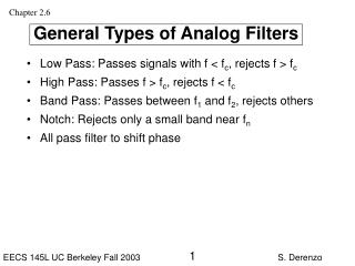
Physics 104. Design & Build Lab Electric Guitar Suh Young Lee(20100384, CE), Ko Tae Sik (20100495, ME) . Chung Se Young (20100503, CH) This project was conducted during Nov. 08 ~ Dec. 10 as an project of Dept of Physics - Design & Build Lab for Freshmen. Principle Introduction High Pass Filter Basic Principles of Guitar Pick up & Inducted Faraday's law of induction (A’: Area of Pickup, the amplitude of oscillation is A, Sine wave) Low Pass Filter High Pass Filter Single Coil Pickup E - 82.4 Hz, A – 110 Hz, D - 146.8 Hz, G – 196 Hz, B - 246.9 Hz, E - 329.6 Hz Iron rod: length=30mm, D=6mm (*6, given) Diameter of coil: D=0.2mm (given) Winding number of coil: 500 times -> 200 times Low Pass Filter Procedure Design Winding up Pickup Conclusion Conclusion Number of Winding = 200 • 0.22μF, 570 Ω를 연결한 Low Pass filter와 0.47μF, 7.57kΩ를 연결한 High Pass filter로 80Hz ~ 1.3 kHz의 Band Width를 가지는 Band Pass filter를 만들었다. 이론적으로 계산하면 44Hz~1269Hz의 값을 가지므로 예상한 값에 잘 부합한다고 할 수 있다. • pre-amp까지 모두 연결한 뒤 스위치를 켜고 줄을 튕겨본 결과 스피커를 통해서 소리가 나는 것을 확인하였으며 이를 통해 회로에 문제가 없다는 것을 확인하였다. 각 현마다 소리의 세기가 차이가 났는데, 각 iron rod마다 코일의 감은 수가 조금씩 다르고 현과의 거리가 다르기 때문인 것으로 보인다. f= 700Hz f= 100Hz Cut Off Frequency ㅍ R=19080Ω C=0.47μF R=216Ω C=0.47μF R=7.57kΩ C=0.47μF R=570Ω C=0.22μF Discussion Results • 현을 튕겼을 때 코일에 의해 유도된 기전력의 크기가 약 6mV로 측정되었다. 만든 스피커를 이용하여 크기를 증폭시킨 후에도 그 소리가 기대했던 것만큼 크지 않았다. 이 소리를 크게 할 수 있는 방법 중 가장 쉽게 생각할 수 있는 것은 코일 감는 수를 늘리는 것인데, 기타 본체와 구멍의 크기를 감안할 때 감는 수에는 제한이 생긴다. 그렇다면 감는 수를 늘리는 것 외에 더 큰 소리를 방법에는 어떤 것들이 있을까? • 자석의 세기 • 픽업과 현과의 거리 • 3. 진폭 • pre-amp의 증폭비율 • 각 현의 기본음을 맞추기 위해 장력을 조절하는 과정에서 나무가 부러지기도 했는데, 이처럼 본체에 무리가 갈 정도의 장력이 걸리기 전에 미리 알 수 있는 방법은 없을까? Resonant frequency = 4870Hz R= 5.47kΩ, C=0.47μF (RLC Series Circuit) L = 2.27mH Band width : 80Hz~ 1.3kHz Low Pass filter : 0.22μF, 570 Ω High Pass filter : 0.47μF, 7.57kΩ References Van Valkenburg, M. E.. Network Analysis (3rd edition ed.). pp. 383–384. ISBN0-13-611095-9.

![[f´‚nE˘RIks]](https://cdn0.slideserve.com/636013/f-ne-riks-dt.jpg)