Materials Engineering – Day 6
Materials Engineering – Day 6. Quiz Review crystal structure Review crystal defects Review dislocations Review the golden rule for strengthening metal. Things that can be used to make metals strong. You need to know/be able to.

Materials Engineering – Day 6
E N D
Presentation Transcript
Materials Engineering – Day 6 Quiz Review crystal structure Review crystal defects Review dislocations Review the golden rule for strengthening metal. Things that can be used to make metals strong.
You need to know/be able to • For the following processes, determine (from graphs and/or calculations) the strength/ductility and describe the governing microstructural mechanism • Solid Solution Strengthening • Grain Size Refinement • Cold Work and Annealing • Name the two types of solid solutions (interstitial and substitutional) and explain how they differ.
Crystallinity in Metals Three types of unit cells. List in order of slip systems. Name a point defect, a line defect, and an area defect. What is the relationship between slip and plastic deformation? What is the relationship between dislocation motion and slip?
Dislocation Motion Dislocations & plastic deformation • Cubic & hexagonal metals - plastic deformation by plastic shear or slip where one plane of atoms slides over adjacent plane by defect motion (dislocations). • If dislocations don't move, deformation doesn't occur! Adapted from Fig. 7.1, Callister 7e.
BLOCK THAT DISLOCATION Bronze sword from Troy We will tell the story of one of the earliest attempts to “block that dislocation” discovered by humans. Our story starts around 700 BC… Chinese bronze from Spring and Autumn period
What’s Happening? The tin atoms dissolve in the matrix of copper. There are many, many substitutional solute atoms. These atoms interact with dislocations, impeding their motion. The solute atoms are not quite the right size. This produces stress and strain in the lattice. The solute atoms’sstess field attracts or repels the stress field around the dislocation. The result is that the dislocation is pinned or blocked – It’s motion is impeded!
“Rules” for substitutional and Interstitial sold solutions • Hume Rothery Rules for substitutional • Similar size • Similar crystal structure • Similar electronegativity • For Interstitial • Solute atom must be small relative to solvent atom so it can fit in the spaces between atoms
Point Defects in Alloys Two outcomes if impurity (B) added to host (A): • Solid solution of B in A (i.e., random dist. of point defects) OR Substitutional solid soln. (e.g., Cu in Ni) Interstitial solid soln. (e.g., C in Fe) • Solid solution of B in A plus particles of a new phase (usually for a larger amount of B) Second phase particle --different composition --often different structure.
Imperfections in Solids Conditions for substitutional solid solution (S.S.) • W. Hume – Rothery rule • 1. r(atomic radius) < 15% • 2. Proximity in periodic table • i.e., similar electronegativities • 3. Same crystal structure for pure metals • 4. Valency • All else being equal, a metal will have a greater tendency to dissolve a metal of higher valency than one of lower valency
Element Atomic Crystal Electro- Valence Radius Structure nega- (nm) tivity Cu 0.1278 FCC 1.9 +2 C 0.071 H 0.046 O 0.060 Ag 0.1445 FCC 1.9 +1 Al 0.1431 FCC 1.5 +3 Co 0.1253 HCP 1.8 +2 Cr 0.1249 BCC 1.6 +3 Fe 0.1241 BCC 1.8 +2 Ni 0.1246 FCC 1.8 +2 Pd 0.1376 FCC 2.2 +2 Zn 0.1332 HCP 1.6 +2 Imperfections in Solids Application of Hume–Rothery rules – Solid Solutions 1. Would you predictmore Al or Ag to dissolve in Zn? 2. More Zn or Al in Cu? Table on p. 106, Callister 7e.
Strengthening by Alloying • small impurities tend to concentrate at dislocations • reduce mobility of dislocation increase strength Adapted from Fig. 7.17, Callister 7e.
Strengthening by alloying • large impurities concentrate at dislocations on low density side Adapted from Fig. 7.18, Callister 7e.
180 400 120 Yield strength (MPa) Tensile strength (MPa) 300 60 200 0 10 20 30 40 50 0 10 20 30 40 50 wt.% Ni, (Concentration C) wt.%Ni, (Concentration C) Ex: Solid SolutionStrengthening in Copper • Tensile strength & yield strength increase with wt% Ni. Adapted from Fig. 7.16 (a) and (b), Callister 7e. • Empirical relation: • Alloying increases sy and TS.
Result Here is the plot in the notes.
Strategies for Strengthening: Reduce Grain Size • Grain boundaries are barriers to slip. • Barrier "strength" increases with Increasing angle of misorientation. • Smaller grain size: more barriers to slip. • Hall-Petch Equation: Adapted from Fig. 7.14, Callister 7e. (Fig. 7.14 is from A Textbook of Materials Technology, by Van Vlack, Pearson Education, Inc., Upper Saddle River, NJ.)
Another Dislocation blocker: The grain boundary A dislocation coming up on the grain boundary will not be able to cross easily into the adjacent grain. It will probably stop waiting for more stress to be applied. Other dislocations will pile up behind it.
Another Blocker: Other Dislocations Recall that as plastic deformation proceeds the density of dislocations increases by several orders of magnitude. So dislocations block themselves! This accounts for the strengthening that occurs during plastic deformation. (Done on purpose, we call it cold work.
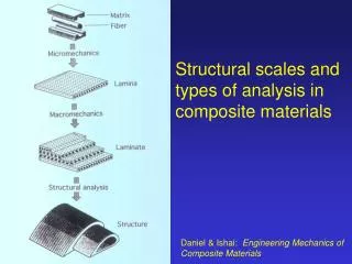
force -Forging -Rolling roll die A d A A A o blank o d Adapted from Fig. 11.8, Callister 7e. roll force -Drawing -Extrusion A o die container A d die holder tensile force A o ram A billet extrusion d force die die container Strategies for Strengthening: Cold Work (%CW) • Room temperature deformation. • Common forming operations change the cross sectional area:
Dislocations During Cold Work 0.9 mm • Ti alloy after cold working: • Dislocations entangle with one another during cold work. • Dislocation motion becomes more difficult. Adapted from Fig. 4.6, Callister 7e. (Fig. 4.6 is courtesy of M.R. Plichta, Michigan Technological University.)
total dislocation length unit volume s large hardening s y1 s small hardening y0 e Result of Cold Work Dislocation density = • Carefully grown single crystal ca. 103 mm-2 • Deforming sample increases density 109-1010 mm-2 • Heat treatment reduces density 105-106 mm-2 • Yield stress increases as rd increases:
Impact of Cold Work As cold work is increased • Yield strength (sy) increases. • Tensile strength (TS) increases. • Ductility (%EL or %AR) decreases. Adapted from Fig. 7.20, Callister 7e.