Download
1 / 28
280 likes | 298 Views
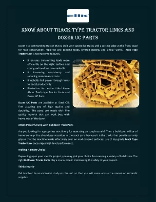
service repair manual

E N D
Service Repair Manual Models D6R TRACK-TYPE TRACTOR
D6R Track-Type Tractor Differential Steering 1RW00001-UP (MACHINE) POWER... 1/8 Shutdown SIS Previous Screen Product: TRACK-TYPE TRACTOR Model: D6R TRACK-TYPE TRACTOR 1RW Configuration: D6R Track-Type Tractor Differential Steering 1RW00001-UP (MACHINE) POWERED BY 3306 Engine Disassembly and Assembly D6R TRACK-TYPE TRACTOR POWER TRAIN Media Number -SENR9496-02 Publication Date -01/11/2004 Date Updated -23/07/2018 SENR94960013 Idlers SMCS - 4159-010; 4159-015; 4159-016 Remove & Install Idlers Start By: a. separate track 1. The weight of idler (1) is 143 kg (315 lb). Fasten a hoist and Tool (A) to idler (1) remove two bolts (3) and washers from each side of the idler. 2. Remove one cap (2) from each side. 3. Lower idler (1) slightly and remove. https://127.0.0.1/sisweb/sisweb/techdoc/techdoc_print_page.jsp?returnurl=/sis... 2020/4/20
D6R Track-Type Tractor Differential Steering 1RW00001-UP (MACHINE) POWER... 2/8 NOTE: It may be necessary to raise the front of the roller frame with a small jack to provide clearance to remove the roller. 4. Remove one block (4) from each side. NOTE: The following steps are for installation of the idler. 5. Fasten a hoist and Tool (A) to idler (1). Put one block (4) on each side of the idler in position on the dowel. NOTICE The hole in idler shaft (5) must be aligned with pin (6) in cap (2). 6. Put the idler in position on roller frame. Align the hole in idler shaft (5) with pin (6) in cap (2). Install cap (2) with bolts (3) and washers. Tighten the bolts to a torque of 570 ± 80 N·m (420 ± 59 lb ft). Remove Tooling (A). End By: a. connect track Disassemble Idlers Start By: a. remove idlers 1. Use a slow speed drill and a 12.7 mm (.50 in) drill bit, and remove plug (4) and stopper (3) from the end of the shaft. https://127.0.0.1/sisweb/sisweb/techdoc/techdoc_print_page.jsp?returnurl=/sis... 2020/4/20
D6R Track-Type Tractor Differential Steering 1RW00001-UP (MACHINE) POWER... 3/8 NOTICE The shaft will be free to fall when the retainers are removed. 2. Remove eight washers and bolts (2) and retainer (1) from both sides of the idler. 3. Remove O-ring seal (6) from retainer (1). NOTE: If the Duo-Cone seals are to be used again, put identification marks on the seals so they can be assembled and installed in their original position. 4. Put identification marks on the Duo-Cone seal (5). Remove Duo-Cone seal (5) from retainer (1). 5. Put identification marks on Duo-Cone seal (7). Remove Duo-Cone seal (7) and toric stabilizer (9) from both sides of shaft (8). 6. Remove washer (10) from both ends of shaft (8). https://127.0.0.1/sisweb/sisweb/techdoc/techdoc_print_page.jsp?returnurl=/sis... 2020/4/20
D6R Track-Type Tractor Differential Steering 1RW00001-UP (MACHINE) POWER... 4/8 7. Pull shaft (8) out of the idler far enough to fasten a hoist to the shaft. 8. Fasten a hoist to shaft (8). Remove the shaft from idler assembly (11). The weight of the shaft is 21 kg (46 lb). Assemble Idlers 1. Clean and inspect all parts for wear or damage. Replace all parts that are worn or damaged. 2. Make sure all parts are free of oil film, dust or other foreign material. Use Isopropyl Alcohol and a clean cloth or paper towel for cleaning. NOTICE The bearing in idler assembly (1) can be damaged when shaft (2) is installed in the idler. 3. Fasten a hoist to shaft (2). Carefully put shaft (2) in position in idler assembly (1). https://127.0.0.1/sisweb/sisweb/techdoc/techdoc_print_page.jsp?returnurl=/sis... 2020/4/20
D6R Track-Type Tractor Differential Steering 1RW00001-UP (MACHINE) POWER... 5/8 4. Put toric stabilizers (3) in position on both ends of shaft (2). NOTE: See Installation of Duo-Cone Floating Seals before installation of any of the Duo-Cone seals. 5. Put toric ring (4) in position in seal ring (5). Make sure the toric ring is straight in seal ring (5). 6. Put ring (4) and seal ring (5) in Isopropyl Alcohol until the entire toric ring is wet. 7. Use Tool (A) to install the toric ring and seal ring (5) on shaft (2). Install the rings until Tool (A) makes contact with the end of shaft (2). 8. Use a depth micrometer (6) to measure the distance between seal ring (5) and the shaft at four locations 90 degrees apart. The difference in these four measurements must not be more than 0.80 mm (.031 in). 9. If adjustments to seal ring (5) are necessary, use Tool (A) to adjust the seal ring on the shaft. 10. Repeat Steps 5 through 9 to install the toric ring and seal ring on the other side of the idler. https://127.0.0.1/sisweb/sisweb/techdoc/techdoc_print_page.jsp?returnurl=/sis... 2020/4/20
D6R Track-Type Tractor Differential Steering 1RW00001-UP (MACHINE) POWER... 6/8 11. Put O-ring seal (8) in position on seal ring (7). Make sure the O-ring seal is straight on the seal ring. 12. Lubricate the O-ring seal on the seal ring with Isopropyl Alcohol. 13. Put the O-ring seal and seal ring (7) in position on retainer (9). Use Tool (A) and an arbor press to install the seal ring in the retainer. Install O-ring seal and seal ring until the O-ring seal makes contact with the bottom of the retainer. 14. Use depth micrometer (6) to measure the distance from the surface of retainer (9) to the surface of seal ring (7) at four locations 90 degrees apart. The difference in these measurements must not be more than 0.30 mm (.012 in). 15. If adjustments to the seal are necessary, use Tool (A) to adjust the seal ring in the retainer. 16. Put O-ring seal (10) in position in the groove in retainer (9). 17. Put Vaseline or grease on O-ring seal (10) to it in place on the retainer. https://127.0.0.1/sisweb/sisweb/techdoc/techdoc_print_page.jsp?returnurl=/sis... 2020/4/20
D6R Track-Type Tractor Differential Steering 1RW00001-UP (MACHINE) POWER... 7/8 18. Install washer (11) on the end of shaft (2). 19. Make sure the faces of the seal rings are clean and free of any foreign material. 20. Put a thin film of clean oil on the faces of the seal rings. 21. Put Tool (B) in position in the bores of retainer (9) and the seal ring. Use Tool (B) to put the seal ring and retainer (9) in their original position on the idler assembly. 22. Use Tool (B) to hold the seal ring and retainer (9) in the correct position on the idler assembly. 23. Install bolts (12). Tighten the bolts evenly to keep retainer (9) in alignment with the idler assembly. 24. Tighten bolts (12) to a final torque of 70 ± 15 N·m (52 ± 11 lb ft). 25. Repeat Steps 11 through 24 to install the retainer on the other side of the idler. 26. Use Tool (D) to pressure test the idler assembly as follows: a. Put air (free of water) under a pressure of 280 kPa (41 psi) in the idler shaft. b. If there is a pressure reduction in ten seconds or less, there is a leak in the idler assembly. The idler assembly must be disassembled and checked. https://127.0.0.1/sisweb/sisweb/techdoc/techdoc_print_page.jsp?returnurl=/sis... 2020/4/20
D6R Track-Type Tractor Differential Steering 1RW00001-UP (MACHINE) POWER... 8/8 27. Use Tool (E) to check the end play of shaft (2). The end play must be 0.25 mm to 0.85 mm (.010 to .034 in). 28. Fill idler shaft (2) with 650 ± 15 mL (22.1 ± .5 oz.) of SAE 30W oil. 29. Put clean oil on stopper (13). Install the stopper in the end of shaft (2). Install the stopper until it is 10 ± 4 mm (.393 ± .16 in) below the surface of the end of the shaft. 30. Use Tool (C) to install plug (14) in the stopper. Install the plug so it is even with the end of the stopper. End By: a. install idler Copyright 1993 - 2020 Caterpillar Inc. Mon Apr 20 12:31:01 UTC+0800 2020 All Rights Reserved. Private Network For SIS Licensees. https://127.0.0.1/sisweb/sisweb/techdoc/techdoc_print_page.jsp?returnurl=/sis... 2020/4/20
D6R Track-Type Tractor Differential Steering 1RW00001-UP (MACHINE) POWER... 1/8 Shutdown SIS Previous Screen Product: TRACK-TYPE TRACTOR Model: D6R TRACK-TYPE TRACTOR 1RW Configuration: D6R Track-Type Tractor Differential Steering 1RW00001-UP (MACHINE) POWERED BY 3306 Engine Disassembly and Assembly D6R TRACK-TYPE TRACTOR POWER TRAIN Media Number -SENR9496-02 Publication Date -01/11/2004 Date Updated -23/07/2018 SENR94960014 Equalizer Bar SMCS - 7206-011; 7206-012; 7206-017 Remove Equalizer Bar https://127.0.0.1/sisweb/sisweb/techdoc/techdoc_print_page.jsp?returnurl=/sis... 2020/4/20
D6R Track-Type Tractor Differential Steering 1RW00001-UP (MACHINE) POWER... 2/8 *Increase thread to 2 1/4" on both ends of 9H1080 stub Start By: a. remove track roller frame 1. Put Tooling (A) in position under the side of the equalizer bar that the track roller frame was not removed. Push the side of the equalizer bar up and remove bar stock (1), that was installed between the frame and the equalizer bar, when the track roller frame was removed. https://127.0.0.1/sisweb/sisweb/techdoc/techdoc_print_page.jsp?returnurl=/sis... 2020/4/20
D6R Track-Type Tractor Differential Steering 1RW00001-UP (MACHINE) POWER... 3/8 2. Put enough wooden blocks (2) under the track roller frame so that when Tooling (A) is removed, the equalizer bar does not make contact with the frame on the side that the track roller frame was removed. Remove Tooling (A). 3. Remove retaining bolt (3) not shown. Install Tooling (B) on the pin. Make sure the FT1713 Wedges [part of Tooling (B)] are put in position between the equalizer bar and the saddle to prevent the pin from binding as it is removed. Use Tooling (B) and remove the equalizer bar pin. 4. Put the FR1713 Wedges [part of Tooling (D)] in between the equalizer bar and the saddle to prevent the pin from binding as it is removed. 5. Remove three bolts (4) and the retainer plate. 6. The weight of the equalizer bar is 143 kg (315 lb). Put Tooling (C) in position under the equalizer bar and fasten wire (5) to Tooling (C) so the equalizer bar will not fall when it is removed. https://127.0.0.1/sisweb/sisweb/techdoc/techdoc_print_page.jsp?returnurl=/sis... 2020/4/20
D6R Track-Type Tractor Differential Steering 1RW00001-UP (MACHINE) POWER... 4/8 7. Install Tooling (D) and remove the equalizer bar center pin. Remove Tooling (D). 8. Lower the equalizer bar with Tooling (C). Remove spacer (6) from each side of the equalizer bar and remove the bar from under the machine. Install Equalizer Bar 1. Position the equalizer bar on Tooling (C). Fasten the equalizer bar with wire (5) to Tooling (C). Put the equalizer bar in position under the machine. 2. Put a small amount of 5P-0960 Multipurpose Type Grease on the two lip seals and on the center equalizer bar bearing. 3. Put two spacers (6) in position, one on each side of the equalizer bar. https://127.0.0.1/sisweb/sisweb/techdoc/techdoc_print_page.jsp?returnurl=/sis... 2020/4/20
D6R Track-Type Tractor Differential Steering 1RW00001-UP (MACHINE) POWER... 5/8 4. Put the equalizer bar in position in the equalizer bar saddle with Tooling (C). NOTICE The 2P2506 Anti-Seize Compound should not be permitted to get in the bearing area of the equalizer bar. 5. Put 2P-2506 Anti-Seize Compound in the front bore of the equalizer bar saddle and on the rear diameter of equalizer bar center pin (7). 6. Align the bores in the equalizer bar saddle with the bore in the equalizer bar. Install equalizer bar center pin (7). Make sure the flats on the end of the pin are horizontal so the retainer plate can be installed properly. 7. Put the retainer plate in position and install three bolts (4). Remove wire (5) and Tooling (C). 8. Align the bore in the equalizer bar and the bores in the track roller frame. Install pin (8) and retaining bolt (3). https://127.0.0.1/sisweb/sisweb/techdoc/techdoc_print_page.jsp?returnurl=/sis... 2020/4/20
D6R Track-Type Tractor Differential Steering 1RW00001-UP (MACHINE) POWER... 6/8 9. Use Tooling (A) to raise the equalizer bar and track roller frame. Remove wooden blocks (2) from under the track roller frame. 10. Put bar stock (1), that was removed earlier, between the equalizer bar and the frame, as shown. It will put the equalizer bar in its original position so the track roller frame can be installed. Lower the equalizer bar and track roller frame. Remove Tooling (B). End By: a. install track roller frame Disassemble & Assemble Equalizer Bar Start By: a. remove equalizer bar https://127.0.0.1/sisweb/sisweb/techdoc/techdoc_print_page.jsp?returnurl=/sis... 2020/4/20
D6R Track-Type Tractor Differential Steering 1RW00001-UP (MACHINE) POWER... 7/8 1. Use a hammer and punch to bend the outside ring of seals (1) toward the center. Do this in several places and remove seals (1). 2. Use Tooling (A) and remove the center bearing from the equalizer bar. 3. Use a hammer and a punch to bend the outside rings of lip seals (2) toward the center. Do this in several places and remove seals (2). Do this at both ends of the equalizer bar. 4. Use Tooling (B) and remove the retaining rings from each side of the spherical bearings. https://127.0.0.1/sisweb/sisweb/techdoc/techdoc_print_page.jsp?returnurl=/sis... 2020/4/20
D6R Track-Type Tractor Differential Steering 1RW00001-UP (MACHINE) POWER... 8/8 5. Use Tooling (C) and remove end bearings (3) from the equalizer bar. NOTE: The following Steps are for assembly of the equalizer bar. 6. Use Tool (B) and install one of the retaining rings in the end of the equalizer bar. Use Tooling (D) and install bearing (3) against the retaining ring. Use Tool (B) and install the other retaining ring. 7. Repeat Step 6 at the opposite end of the equalizer bar. Put 5P0960 Multipurpose Type Grease on the spherical surface of bearings (3) and in the pin bores. 8. Put 5P3413 Pipe Sealant with Teflon on the inner diameter surfaces of the equalizer bar and install lip seals (2) at the center bore. 9. Put 6V1541 Quick Cure Primer on the center pin bore of the equalizer bar and allow it to dry. Put 9S3265 Retaining Compound on the center bore. 10. Use Tooling (E) and install the center bearing in the equalizer bar. The bearing should be installed so it is the same distance from the front and the rear of the equalizer bar. 11. Put 5P3413 Pipe Sealant with Teflon on the inner diameter of the equalizer bar and install seals (1) on each side of the bearing. End By: a. install equalizer bar Copyright 1993 - 2020 Caterpillar Inc. Mon Apr 20 12:31:50 UTC+0800 2020 All Rights Reserved. Private Network For SIS Licensees. https://127.0.0.1/sisweb/sisweb/techdoc/techdoc_print_page.jsp?returnurl=/sis... 2020/4/20
D6R Track-Type Tractor Differential Steering 1RW00001-UP (MACHINE) POWER... 1/2 Shutdown SIS Previous Screen Product: TRACK-TYPE TRACTOR Model: D6R TRACK-TYPE TRACTOR 1RW Configuration: D6R Track-Type Tractor Differential Steering 1RW00001-UP (MACHINE) POWERED BY 3306 Engine Disassembly and Assembly D6R TRACK-TYPE TRACTOR POWER TRAIN Media Number -SENR9496-02 Publication Date -01/11/2004 Date Updated -23/07/2018 SENR94960015 Pivot Shaft (Stub Shaft) SMCS - 4153-010 Remove & Install Pivot Shaft (Stub Shaft) Start By: a. remove track roller frame 1. Attach a hoist to Tooling (A). Use a nylon strap and attach it to Tooling (A). 2. The weight of stub shaft (1) is 67 kg (148 lb). Remove eight bolts (2) and the stub shaft. NOTE: The following Steps are for installation of the stub shaft. 3. Put 5P-3931 Anti-Seize Compound on the pilot diameter that goes in the main case and frame. https://127.0.0.1/sisweb/sisweb/techdoc/techdoc_print_page.jsp?returnurl=/sis... 2020/4/20
D6R Track-Type Tractor Differential Steering 1RW00001-UP (MACHINE) POWER... 2/2 4. Use a hoist and Tooling (A), put stub shaft (1) in position, and install eight bolts (2). End By: a. install track roller frame Copyright 1993 - 2020 Caterpillar Inc. Mon Apr 20 12:32:39 UTC+0800 2020 All Rights Reserved. Private Network For SIS Licensees. https://127.0.0.1/sisweb/sisweb/techdoc/techdoc_print_page.jsp?returnurl=/sis... 2020/4/20
D6R Track-Type Tractor Differential Steering 1RW00001-UP (MACHINE) POWER... 1/5 Shutdown SIS Previous Screen Product: TRACK-TYPE TRACTOR Model: D6R TRACK-TYPE TRACTOR 1RW Configuration: D6R Track-Type Tractor Differential Steering 1RW00001-UP (MACHINE) POWERED BY 3306 Engine Disassembly and Assembly D6R TRACK-TYPE TRACTOR POWER TRAIN Media Number -SENR9496-02 Publication Date -01/11/2004 Date Updated -23/07/2018 SENR94960016 Final Drive Planetary Carriers (In Chassis) SMCS - 4092-011; 4092-012 Remove Final Drive Planetary Carriers (In Chassis) https://127.0.0.1/sisweb/sisweb/techdoc/techdoc_print_page.jsp?returnurl=/sis... 2020/4/20
D6R Track-Type Tractor Differential Steering 1RW00001-UP (MACHINE) POWER... 2/5 1. Position the final drive drain plug (3) on the bottom as shown. Remove drain plug (3) and drain approximately 11.4 liters (3 U.S. gal.) of oil from the final drive. 2. Remove the center cover. Remove the O-ring seal from the cover. 3. Use Tooling (A) and remove outer axle (2). NOTICE Three bolts [Tooling (B)] must be threaded in 25.4 mm (1 in) to hold the planetary carrier. 4. Remove three equally spaced bolts that hold planetary carrier (5) to hub (4). Install Tooling (B) in place of three bolts as shown. 5. Remove the remaining bolts (1) that hold the planetary carrier to the hub. 6. Use a pry bar and move planetary carrier (5) out of the hub as far as the bolts [Tooling (B)] will permit. https://127.0.0.1/sisweb/sisweb/techdoc/techdoc_print_page.jsp?returnurl=/sis... 2020/4/20
D6R Track-Type Tractor Differential Steering 1RW00001-UP (MACHINE) POWER... 3/5 7. Adjust the upper hanger bracket on Tooling (C) so distance (X) is 203 mm (8 in). Install lower plate (6) so the spacers are down and toward the vertical leg of the bracket. 8. Attach a hoist to Tooling (C) and install it on the planetary carrier. 9. The weight of the planetary carrier is 132 kg (290 lb). Remove the three bolts [Tooling (B)] and remove planetary carrier (5) from the hub. Remove the O-ring seal. 10. To disassemble the planetary carrier, see Disassemble Final Drive in this module. Ring gear (8) will be free to fall when retainer (7) is removed. To prevent possible personal injury, Tooling (D) and (E) must be in position to hold ring gear (8) and the hub in position when retainer (7) is removed. 11. Put Tooling (D) under final drive hub (4) to hold it in position when retainer (7) is removed. Install Tooling (E) to hold ring gear (8) in position. Use the bolts that hold the planetary carrier in position to install Tooling (E). 12. Remove the bolts and retainer (7). 13. Remove the lip seal from the end of the spindle. https://127.0.0.1/sisweb/sisweb/techdoc/techdoc_print_page.jsp?returnurl=/sis... 2020/4/20
D6R Track-Type Tractor Differential Steering 1RW00001-UP (MACHINE) POWER... 4/5 Install Final Drive Planetary Carriers (In Chassis) 1. Use Tooling (F) and install lip seal (9) in the end of the spindle. The lip of the seal must be toward the inside of the spindle. Put clean oil on the lip of the seal. 2. Put retainer (7) in position on the spindle and install the bolts that hold it. Tighten the bolts to a torque of 135 ± 15 N·m (100 ± 11 lb ft). 3. Remove Tooling (D) and (E) from the final drive. https://127.0.0.1/sisweb/sisweb/techdoc/techdoc_print_page.jsp?returnurl=/sis... 2020/4/20
D6R Track-Type Tractor Differential Steering 1RW00001-UP (MACHINE) POWER... 5/5 4. For assembly of the planetary carriers, see topic, Assemble Final Drive in this module. 5. Install the O-ring seal on the planetary carrier. 6. Use Tooling (C) and a hoist and put the planetary carrier in position on the hub. Push the planetary carrier in until it is approximately 25.4 mm (1 in) from the hub. 7. Thread three bolts [Tooling (B)] in 25.4 mm (1 in), evenly spaced, to support the planetary carrier. Remove Tooling (C). 8. Install bolts (1). Remove Tooling (B) and install the remaining three bolts that hold the planetary carrier to the hub. 9. Use Tooling (A) and install outer axle (2). 10. Install the O-ring seal on the cover and install the cover on the final drive. 11. Drain plug (3) must be toward the bottom. Fill the final drive with oil to the bottom of the fill plug. See the Operation And Maintenance Guide for the correct oil and the capacity. Copyright 1993 - 2020 Caterpillar Inc. Mon Apr 20 12:33:28 UTC+0800 2020 All Rights Reserved. Private Network For SIS Licensees. https://127.0.0.1/sisweb/sisweb/techdoc/techdoc_print_page.jsp?returnurl=/sis... 2020/4/20
Thank you very much for your reading. Please Click Here. Then Get COMPLETE MANUAL. NO WAITING NOTE: If there is no response to click on the link above, please download the PDF document first and then click on it.
D6R Track-Type Tractor Differential Steering 1RW00001-UP (MACHINE) POWER... 1/12 Shutdown SIS Previous Screen Product: TRACK-TYPE TRACTOR Model: D6R TRACK-TYPE TRACTOR 1RW Configuration: D6R Track-Type Tractor Differential Steering 1RW00001-UP (MACHINE) POWERED BY 3306 Engine Disassembly and Assembly D6R TRACK-TYPE TRACTOR POWER TRAIN Media Number -SENR9496-02 Publication Date -01/11/2004 Date Updated -23/07/2018 SENR94960017 Final Drives SMCS - 4050-011; 4050-012; 4050-015; 4050-016 Remove Final Drives Start By: a. separate track NOTE: The final drive planetary carriers can be removed in chassis. See topic, Remove Final Drive Planetary Carriers (In Chassis). 1. Turn the final drive until drain plug (1) is on the bottom as shown. Remove drain plug (1) and drain approximately 13.2 liters (3.4 U.S. gal.) of oil from the final drive. https://127.0.0.1/sisweb/sisweb/techdoc/techdoc_print_page.jsp?returnurl=/sis... 2020/4/20
D6R Track-Type Tractor Differential Steering 1RW00001-UP (MACHINE) POWER... 2/12 2. Remove the cover from the final drive and remove the O-ring seal from the cover. 3. Install Tooling (A) and remove the outer axle. 4. Adjust the top bracket on Tooling (B) so that dimension (X) is 213 mm (8.4 in). The lower mounting bracket must be installed with the spacers outward as shown. 5. Remove two of the bolts from the sprocket segments. Fasten a hoist and install Tooling (B) on the final drive. NOTICE Bolts (4) hold the steering clutch and brake to the main case and frame. Do not remove bolts (4). https://127.0.0.1/sisweb/sisweb/techdoc/techdoc_print_page.jsp?returnurl=/sis... 2020/4/20
D6R Track-Type Tractor Differential Steering 1RW00001-UP (MACHINE) POWER... 3/12 6. Remove bolts (2) that hold the final drive to the main case and frame. 7. The weight of the final drive is 490 kg (1075 lb). Remove four bolts (3) that hold the final drive and steering clutch and brake together. 8. Use Tooling (B) and remove the final drive from the machine. 9. Remove the O-ring seal from either the face of the steering clutch or the final drive hub. Install Final Drives 1. Inspect the condition of O-ring seals and replace if necessary. 2. Put the O-ring seal in position on the face of the steering clutch. 3. Fasten a hoist and install Tooling (B) on the final drive. Adjust Tooling (B) if necessary to put the final drive in a level position. https://127.0.0.1/sisweb/sisweb/techdoc/techdoc_print_page.jsp?returnurl=/sis... 2020/4/20