Download
1 / 22
220 likes | 444 Views
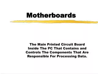
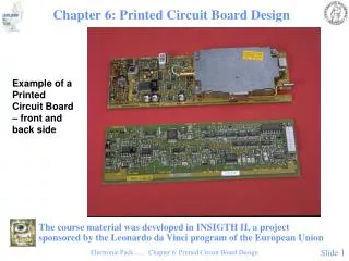
Preparing Printed Circuit Boards (PCB’s) for Flight Computers. AEM 1905, Fall 2008. Begin with copper-covered plastic sheet called PCB Laminate. Cut the PCB Laminate to size (I used a radial-arm saw). Deburr the edges (I used a Dremel tool with a grinding stone on it).

E N D
Preparing Printed Circuit Boards (PCB’s) for Flight Computers AEM 1905, Fall 2008
Deburr the edges (I used a Dremeltool with a grinding stone on it).
Print the circuit pattern in ink with a laser printer onto glossy photo paper.
Scour the boards with a Scotch-brite pad then rinse with acetone. Notice the fingerprints on the board which has not been scoured yet.
Use an iron (no steam!) on the hottest setting to iron the pattern onto the copper surface. Press down hard for about 3 min.
Another option is to iron the pattern onto the board rolling on a dowel – easier to apply more pressure to every point on the board.
Soak the board in hot water for about 10 minutes to soften the paper for removal.
After soaking, remove as much backing paper as possible with the fingers. The ink pattern will stick to the copper below.
After cleaning off as much paper as possible by hand, use a toothbrush to scrub the surface some more. The ink should not come off the copper at all during this process.
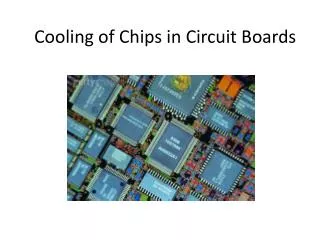
Here is a set of boards, ready for etching. The ink serves as a “etch mask” to protect the copper when it is submerged in etchant.
Copper etching is done in a fume hood while taking proper safety precautions.
Etching is done with a solution that is two parts hydrogen peroxide to one part muriatic acid. Acetone is used for clean-up.
Used etchant (and used acetone) are disposed of as hazardous waste.
When immersed in etchant for a few minutes the exposed copper is dissolved. This board is not quite done near the bottom edge.
Continuously agitate the solution while etching, always wearing gloves. The etch solution turns greens from the copper.
Here is a demonstration board that was inten-tionally only dipped half-way into the etchant.
Here is a fully-etched board, ready for clean up. The plastic under where there used to be copper is actually white.
Use acetone to wash off the ink etch mask. At right is a set of finished boards, all of which have been etched (because the plastic looks white) but only 3 of which have been cleaned.
Drill holes in the PCB (I use a Dremel tool drill press and a #64 bit for use with PCB’s). Drill gently – it is easy to break off a drill bit that small.