Download
1 / 59
590 likes | 611 Views
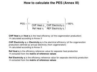
Explore how computers calculate using ALU, registers, and CPU. Learn about ALU functions, binary math, overflow, and better solutions. Dive into CPU architecture principles and operation.

E N D
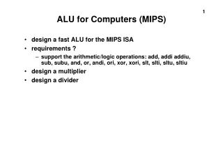
5 - How Computers Calculate - the ALU CS 1 Introduction to Computers and Computer Technology Rick Graziani Spring 2017
Crash Course Videos 5 through 9 • More than we will cover • Watch: 5 - How Computers Calculate - the ALU • Watch for your own interest (Additional information coinciding with this presentation) • 6 - Registers and RAM • 7 - The Central Processing Unit (CPU) • 8 - Instructions & Programs • 9 - Advanced CPU Designs Rick Graziani graziani@cabrillo.edu
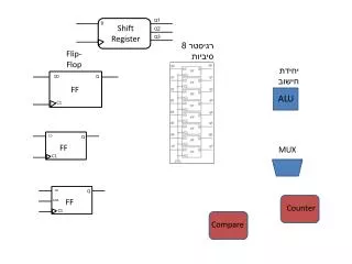
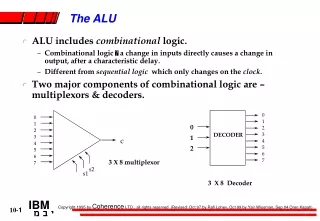
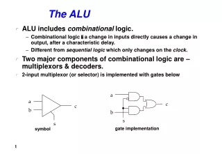
Computer Architecture • Central Processing Unit (CPU) or processor • Arithmetic/Logic unit (ALU) • Arithmetic Unit performs arithmetic operations on data such as addition and subtraction • Logic Unit performs boolean operations and simple numerical tests such as negative or positive • Control unit • Coordinating the CPU’s activities • Holds input and results (output) for the ALU • Registers • Temporary storage for the CPU • General registers • Special purpose registers Rick Graziani graziani@cabrillo.edu
5 - How Computers Calculate - the ALU Rick Graziani graziani@cabrillo.edu
Full Adder Table Rick Graziani graziani@cabrillo.edu
Full Adder Table Rick Graziani graziani@cabrillo.edu
Using Logicly Rick Graziani graziani@cabrillo.edu
Binary Math - Addition 12864’s32’s16’s8’s4’s2’s1’s 0 0 1 1 1 0 1 0 + 0 0 0 1 1 0 1 1 -------------------------------------- Dec 1 1 1 1 58 + 27 ----- 0 1 0 1 0 1 0 1 85 Rick Graziani graziani@cabrillo.edu
Full Adder Table Rick Graziani graziani@cabrillo.edu
Overflow • What happens when we only have storage for an 8-bit number and we need more than 8 bits? • Overflow – Occurs when the result of an addition is TOO LARGE to be represented by the number of bits you are using. • Causes errors and unexpected behavior 128’s64’s32’s16’s8’s4’s2’s1’s 1 1 1 1 1 1 1 1 + 1 -------------------------------------- 1 1 1 1 1 1 1 1 0 0 0 0 0 0 0 0 Rick Graziani graziani@cabrillo.edu
Original Pacman Arcade Game Level 255 = 11111111 Level 256 = &^$^%#& Rick Graziani graziani@cabrillo.edu
One Solution • One solution: More adders, but means more gates Rick Graziani graziani@cabrillo.edu
Better Solutions • Carry-Look-Ahead Adder • Simple (less expensive) ALUs do not have multiplication or division operations (such as those in your thermostat, microwave or remote) • For example, to multiply they add multiple times. • Computers such as laptops and cell phones have a dedicated processor for tasks like multiplication. • More complicated and more expensive. Rick Graziani graziani@cabrillo.edu
Intel 74181 • First ALU on a chip (1970) Rick Graziani graziani@cabrillo.edu
A CPU can be: A CPU can be: 1. A series of integrated circuits (chips) on one or more circuit boards • Older mainframe and minicomputers 2. On a single integrated circuit known as a microprocessor microprocessor = a CPU on a single chip microcomputer = older term for a computer with a microprocessor(s) (PC, Macintosh) Rick Graziani graziani@cabrillo.edu
Computer Architecture • Bus • Used to transfer bits between the CPU and RAM (main memory) Rick Graziani graziani@cabrillo.edu
User interface User Types (Input) 2 + = 3 Computer Outputs 5 Rick Graziani graziani@cabrillo.edu
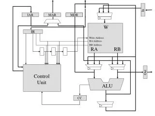
Computer Architecture • Task: Add two values stored in main memory (RAM) • Data (two values) must be transferred from main memory to registers within the CPU • ALU: Values are added • Result stored in main memory (RAM) Value = 5 2 + 3 = 5 Value = 2 Value = 3 Rick Graziani graziani@cabrillo.edu
Computer Architecture • Task: Add two values stored in main memory (RAM) • Data (two values) must be transferred from main memory to registers within the CPU • ALU: Values are added • Result stored in main memory (RAM) 2 + 3 = 5 5 2 2 3 3 2 + 3 = 5 Rick Graziani graziani@cabrillo.edu
Our CPU and the Pentium CPU Rick Graziani graziani@cabrillo.edu
Stored Program Concept • Stored program concept: A program can be encoded as bit patterns and stored in main memory. • CPU can then: • extract the instructions as needed (copy them into its registers) • execute them Program instruction Rick Graziani graziani@cabrillo.edu
Terminology • Machine instruction: An instruction (or command) encoded as a bit pattern recognizable by the CPU • Machine language: The set of all instructions recognized by a machine (CPU) Op-code Operand Description 1 RXY LOAD reg. R from cell XY. 2 RXY LOAD reg. R with XY. 3 RXY STORE reg. R at XY. 4 0RS MOVE R to S. 5 RST ADD S and T into R. (2’s comp.) 6 RST ADD S and T into R. (floating pt.) 7 RST OR S and T into R. 8 RST AND S and T into R. 9 RST XOR S and T into R. A R0X ROTATE reg. R X times. B RXY JUMP to XY if R = reg. 0. C 000 HALT. Rick Graziani graziani@cabrillo.edu
Op-code Operand Description 1 RXY LOAD reg. R from cell XY. 2 RXY LOAD reg. R with XY. 3 RXY STORE reg. R at XY. 4 0RS MOVE R to S. 5 RST ADD S and T into R. (2’s comp.) 6 RST ADD S and T into R. (floating pt.) 7 RST OR S and T into R. 8 RST AND S and T into R. 9 RST XOR S and T into R. A R0X ROTATE reg. R X times. B RXY JUMP to XY if R = reg. 0. C 000 HALT. Machine Language Philosophies • Reduced Instruction Set Computing (RISC) • Few, simple, efficient, and fast instructions • Examples: PowerPC from Apple/IBM/Motorola and SPARK from Sun Microsystems • Complex Instruction Set Computing (CISC) • Many, convenient, and powerful instructions • Example: Pentium from Intel This slide is now just an FYI Analogy • Chinese characters: (CISC) • More complex than English (RISC) words • 200 English letters might require only 20 Chinese characters. • Chinese requires fewer symbols • Saves on both paper and postage. • However, reading and writing Chinese is more complex • Because each symbol contains more information • The English words are analogous to RISC instructions, • Chinese symbols are analogous to CISC instructions. Rick Graziani graziani@cabrillo.edu
Machine Instruction Types • Machine Instruction Types • Data Transfer: Copy data from one location to another • Arithmetic/Logic: Use existing bit patterns to compute a new bit patterns • Control: Direct the execution of the program • More in a moment Op-code Operand Description 1 RXY LOAD reg. R from cell XY. 2 RXY LOAD reg. R with XY. 3 RXY STORE reg. R at XY. 4 0RS MOVE R to S. 5 RST ADD S and T into R. (2’s comp.) 6 RST ADD S and T into R. (floating pt.) 7 RST OR S and T into R. 8 RST AND S and T into R. 9 RST XOR S and T into R. A R0X ROTATE reg. R X times. B RXY JUMP to XY if R = reg. 0. C 000 HALT. Rick Graziani graziani@cabrillo.edu
Adding values stored in memory 2 3 2+3=5 5 Rick Graziani graziani@cabrillo.edu
Using machine language Rick Graziani graziani@cabrillo.edu
Computer Architecture 2 + 3 = 5 6E 5 0 5 6C 2 5 2 6 3 6D 3 Rick Graziani graziani@cabrillo.edu
Adding values stored in memory Step 1 2 + 3 = 5 6E 5 0 5 Step 2 6C 2 5 2 6 3 6D 3 Step 3 Step 4 Step 5 • Data Transfer • Instructions that request the movement (copying) of data from one location to another Rick Graziani graziani@cabrillo.edu
Adding values stored in memory Step 1 2 + 3 = 5 6E 5 0 5 Step 2 6C 2 5 2 6 3 6D 3 Step 3 Step 4 Step 5 • ALU • Instructions that tells the control unit to request an activity within the ALU • Capable of performing operations other than basic arithmetic operations, including: AND, OR, XOR. Rick Graziani graziani@cabrillo.edu
Remember our half-adder? Adding two bits • Adding two, eight bit values involves a similar process, just more gates (2 + 3 = 5): • 00000010 + 00000011 = 00001001 XOR 0 Inputs: A, B S = Sum C = Carry 1 1 0 AND C S 0 + 1 ---- A + B = 2’s1’s 0 1 = 0 1 1 Rick Graziani graziani@cabrillo.edu
Adding values stored in memory Step 1 Step 2 Step 3 Step 4 Step 5 • Control • Instructions that direct the execution of the program Jump or Branch instructions: Directs the CPU to execute an instruction other than the next one in the list. • Unconditional Jump: Skip to Step 6 • Condition Jump: If the value is 0 then Skip to Step 6 Rick Graziani graziani@cabrillo.edu
The architecture of our machine Address 00000000 00000001 00000010 00000011 11111111 • Main Memory • 256 cells: 00 through FF (Hex) • 0000 0000 through 1111 1111 • Storage: 8 bits per cell • CPU • 16 registers: 0 through F (Hex); 8 bits per cell • Program counter: (Address of) Keeps track of the next instruction • Instruction register: Contains the current instruction to be executed by the ALU. Rick Graziani graziani@cabrillo.edu
Converting Decimal, Hex, and Binary Dec. Hex. Binary Dec. Hex. Binary 0 0 0000 8 8 1000 1 1 0001 9 9 1001 2 2 0010 10 A 1010 3 3 0011 11 B 1011 4 4 0100 12 C 1100 5 5 0101 13 D 1101 6 6 0110 14 E 1110 7 7 0111 15 F 1111 1 Hex digit = 4 bits Rick Graziani graziani@cabrillo.edu
Loading instructions into the computer Rick Graziani graziani@cabrillo.edu
Op-code Operand Description 1 LOAD reg. R from cell XY. 2 LOAD reg. R with XY. 3 STORE reg. R at XY. 4 MOVE R to S. 5 ADD S and T into R. (2’s comp.) 6 ADD S and T into R. (floating pt.) 7 OR S and T into R. 8 AND S and T into R. 9 XOR S and T into R. A ROTATE reg. R X times. B JUMP to XY if R = reg. 0. C HALT. Parts of a Machine Instruction Machine Language • Each instruction involves two parts: • Op-code: Specifies which operation to execute • LOAD, ADD, STORE, etc. • Operand: Gives more detailed information about the operation • Interpretation of operand varies depending on op-code 0011 0101 1010 0111 Binary (16 bits) 1 Hex digit = 4 bits Rick Graziani graziani@cabrillo.edu
Op-code Operand Description 1 LOAD reg. R from cell XY. 2 LOAD reg. R with XY. 3 STORE reg. R at XY. 4 MOVE R to S. 5 ADD S and T into R. (2’s comp.) 6 ADD S and T into R. (floating pt.) 7 OR S and T into R. 8 AND S and T into R. 9 XOR S and T into R. A ROTATE reg. R X times. B JUMP to XY if R = reg. 0. C HALT. Parts of a Machine Instruction Store the bits found in register 5 in main memory cell A7 A 7 8 8 5 1010 0111 Rick Graziani graziani@cabrillo.edu
The machine cycle Rick Graziani graziani@cabrillo.edu
Program Execution Rick Graziani graziani@cabrillo.edu
The program is stored in main memory ready for execution 1 Hex digit = 4 bits Hard Disk Drive 00 FF • The program is copied put into main memory. • Typically from permanent storage. • Requires two memory cells per instruction: • Instructions are 16 bits; memory cells are 8 bits • Program counter contains first instruction: A0 Rick Graziani graziani@cabrillo.edu
Performing the fetch step of the machine cycle Rick Graziani graziani@cabrillo.edu
Program Counter Registers • At the beginning of the first fetch: • Program Counter = A0 A0 0 5 Instruction Register 6 … 02 6C 6D 03 6E Rick Graziani graziani@cabrillo.edu
Program Counter Registers • At the beginning of the first fetch: • Instruction at A0 (and A1) loaded into Instruction register • Program Counter = A2 0 A2 A0 5 Instruction Register 6 156C … 6C 02 6D 03 6E Rick Graziani graziani@cabrillo.edu
Program Counter Registers • CPU analyzes the instruction • Loads Register 5 with the contents of memory cell address 6C. A2 0 5 02 Instruction Register 6 156C … 6C 02 Loadregister 5 in main memory cell 6C 6D 03 6E Rick Graziani graziani@cabrillo.edu
Program Counter Registers • At the beginning of the next fetch: • Program Counter = A2 A2 0 5 02 Instruction Register 6 … 6C 02 6D 03 6E Rick Graziani graziani@cabrillo.edu
Program Counter Registers • Instruction at A2 (and A3) loaded into Instruction register • Program Counter incremented: A4 • CPU analyzes the instruction • Loads Register 6 with the contents of memory cell address 6D. A4 A2 0 5 02 Instruction Register 6 03 166D … 6C 02 Loadregister 6 in main memory cell 6D 6D 03 6E Rick Graziani graziani@cabrillo.edu
Program Counter Registers • At the beginning of the next fetch: • Program Counter = A4 A4 0 2 02 Instruction Register 3 03 … 6C 02 6D 03 6E Rick Graziani graziani@cabrillo.edu
Program Counter Registers • Instruction at A4 (and A5) loaded into Instruction register • Program Counter incremented: A6 • CPU analyzes the instruction • Adds contents of register 5 and register 6, storing the result into register 0. A6 A4 0 05 5 02 Instruction Register 6 03 5056 … 6C 02 Add: result into register 0, adding contents ofregister 5 and register 6 6D 03 6E Adds contents of register 5 and 6, placing result into register 0. Rick Graziani graziani@cabrillo.edu
Program Counter Registers • At the beginning of the next fetch: • Program Counter = A6 A6 0 05 2 02 Instruction Register 3 03 … 6C 02 6D 03 6E Rick Graziani graziani@cabrillo.edu
Program Counter Registers • Instruction at A6 (and A7) loaded into Instruction register • Program Counter incremented: A8 • CPU analyzes the instruction • Stores contents of register 0 in the memory cell at address 6E. A8 0 05 A6 5 02 Instruction Register 6 03 306E … 6C 02 Store contents of register 0, in memory celladdress 6E 6D 03 6E 05 Rick Graziani graziani@cabrillo.edu
Program Counter Registers • At the beginning of the next fetch: • Program Counter = A8 A8 0 05 5 02 Instruction Register 6 03 … 6C 02 6D 03 6E 05 Rick Graziani graziani@cabrillo.edu