Download
1 / 20
200 likes | 420 Views
THE RAPID DEVELOPMENT OF A CLOSED-LOOP CONTROL SYSTEM. 一种闭环控制系统的快速开发. ZHONG-QIANG DING Singapore Institute of Manu during Technology, 71 Nanyang Drive, Singapore 638075 zgding@SIMTech.a-star.edu.sg KECK VOON L1NG School of Electric and Electrical Engineering,

E N D
THE RAPID DEVELOPMENT OF A CLOSED-LOOP CONTROL SYSTEM 一种闭环控制系统的快速开发
ZHONG-QIANG DING Singapore Institute of Manu during Technology, 71 Nanyang Drive, Singapore 638075 zgding@SIMTech.a-star.edu.sg KECK VOON L1NG School of Electric and Electrical Engineering, Nanyang Technological ZJniversity, Nanyang Avenue, Singapore 639798 ekvling@ntu.edu.sg KIAH MOK GOH Singapore Institute of Maw扣during Technology, 71 Nanyang Drive, Singapore 638075 kmgoh@SIMTech.a-star.edu.sg
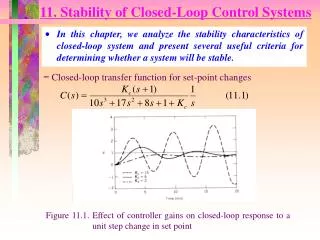
In this paper, the methods to rapidly deploy closed-loop control systems are presented. A flexible real-time embedded platform based on reconfigurable computing technologies is established, on which control blocks consisting of optimized control algorithms are set up. By employing control blocks, a set of tools aiming to shorten the development cycle of embedded control systems are developed. Compare to conventional ways, the tools give controller developers much faster ways to construct required controllers with higher flexibility. keyword:Automatic design; flexible automation; closed-loop control; controller 论文介绍一种快速配置闭环控制系统的方法,建立了一个基于可重构计算技术的实时嵌入式平台,通过使用控制时钟,发展了一个用于缩短嵌入式控制系统开发周期的工具.与传统相比,这个工具帮助控制器开发者更快地更灵活地建立控制器
1. Introduction The research on methodologies of shortening development cycles of complex systems has been an important area of design automation and was captured more attention in recent years [1-3]. Although automatic design and implementation are still in an early experimental stage, more and more researchers realize that it is possible to partially implement the design automation to reduce the development time. Furthermore, it has been shown that for a step-wise mechatronic system realization, the structure of the information-processing hardware and software must be closely related to that of the mechanical, hydraulic, and electrical components [1]. It is thus necessary to design a reconfigurable platform enabling the rapid deployment of hardware and software components, on which control systems can be implemented. 有可能也有必要设计一个可重构的平台,可以在上面快速地实现硬件软件的配置
The organization of this paper is as follows. Section 2 serves the centerpiece of the paper and presents the chip-level optimization methods of control algorithms and provides the designs of control blocks. Section 3 describes a set of software tools used to quickly construct control systems. For an illustration a closed-loop control system called inverted PP 300 rotary inverted pendulum system is provided as test case. A brief conclusion in Sec. 4 is given. 介绍文章结构:第二章是芯片级控制算法的优化方法和控制结构的设计,也是全文的重 点,第三章介绍一个软件工具和PP300环形倒立摆控制系统的测试,第四章总结
1.1. The PP 300 Rotary inverted pendulum The Rotary Inverted Pendulum is widely used for the study of control algorithms. The apparatus (KRi Inverted Pendulum PP300) used is supplied by Kent Ridge Instruments (Singapore) [4]. The PP300 Rotary Inverted Pendulum consists of three main components as illustrated in Fig. 1 (a): a short arm, a pendulum rod and a DC servo motor.(短臂,摆杆,直流伺服电机)
1.2. The reconfigurable platform(可重构平台) The reconfigurable gate arrays are prefabricated, reprogrammable integrated circuits that can be configured to implement the desired circuitry in a matter of seconds [2, 5]. In recent years, the reconfigurable gate array has evolved from a capacity of thousands of gates to millions of gates to allow the implementation of more complex applications. It has also evolved into fully reconfigurable systems and fast co-processors. The dual characteristics of both of hardware and software make a modular assembly of systems possible. The real-time processing guarantees the high performance of delivered systems. The development board shown in the Fig. 1(b) is designed as an experimental platform together with software tools to demonstrate the concepts of rapid development. 可重构门序列是预制的可多次编程的集成电路,它速度很快,近年来获得了广泛的应用,使系统模块化组装成为可能,实时处理保证了系统的性能
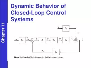
1.3. Closed-loop control systems • Although system functionalities may be differed from control systems to control systems,the control algorithms (PID, MPC, etc.) employed are the core function modules.Furthermore, the development cycles and performance of the systems are also mainly determined by the implementation of those algorithms[6]. When those algorithms are implemented on the reconfigurable hardware, the first issue raised is how to reach high performances of algorithms with limited hardware resources. The second issue raised is how to have a general chip-level design model, in which modules and algorithms can be reconfigured. • 各种控制系统的功能可能不同,不过控制算法的配置都是控制系统中的核心功能,而且控制算法影响开发周期和系统性能..控制算法应用到可重构硬件的时候,第一要考虑怎样在有限的硬件资源上达到高性能,二是怎么设计一般性的芯片级设计模型,使模块和算法可以在上面重构.
Input: one matrix A with n x l elements and one matrix B with l x m elements • Output: one matrix C with n x m elements • Begin • Stepl. Choose Nc. (number of computing cells) • Set j=1 (initialize clock cycle count) • Step2. For each clock cycle j • Xl <- Bj;Xk+1 <- Xk;j <- j+1;k=1,2,...,j; • If Nc<j,then stop • Step3. Set j=1 (initialize clock cycle count) • For each clock cycle j • Cj <-A1xXj;Ck <-A j-k+1x Xk;j } j+1;k=1,2,...,j; • If l<j,then stop • End
If it is assumed that the n is the maximum of three variables: n, m and 1, then the computation complexity in the conventional ways is O(n3 ).The maximum computation complexity after the proposed algorithm is O(n2一n+1) and then can be deduced asO(n2).For example, if the clock rate is 100 clock cycles/ps, simulated on the testing platform, the computational delay of the proposed algorithm, for the two 5x5 matrices, is 0.29 ps similar to the theoretical results, while the computational delay of the conventional algorithm is 1.40 ps. It can be seen that the computation speed by the proposed algorithm is almost five times faster than that by the conventional algorithm. • 算法改进的效果,例子:时钟为100时钟周期/秒的话,要相乘两个5*5的矩阵,新算法用了0.29ps,旧算法用了1.4ps,新算法比旧算法快了5倍
2. Control Blocks(控制结构) • 2.1. Analogy-to-digital converter • This block is used to obtain the angular position of the pendulum from the potentiometer voltage signal. One conventional 12-bit ADC MCP3201 manufactured by Microchip is employed to interface to the reconfigurable chip. The potentiometer outputs an analog voltage of 0 to 5V, depending on the position of the pendulum. • 模数转换用于获得摆杆的角位置,传统上用MCP3201
2.2. Pulse width modulation(脉宽调制) • This block is used to generate a PWM (Pulse Width Modulation) signal of a required duty cycle. • 2.3. Encoder • This block aims to monitor the velocity, position and direction of rotation of the pendulum arm. The optical encoder with three channel outputs is employed, in which a change in the angular position is translated into two electrical pulses, producing a pair of square waves with the same frequency, determined by the speed of rotation of the arm, but are 90 degrees out of phase with each other. • 光电编码器用于监控摆杆臂转动的速度位置和方向
2.4. Control algorithm optimization • Control algorithms must be optimized in terms of resource usages and computational complexity when they are implemented on chip. The computational burdens mainly come from the computational loads of matrix multiplication; one algorithm is thus proposed to lower the computational complexity by the design of dataflow pipelining and parallel processing of computing units. One computing unit named computing cell, consisting of one accumulator and one multiplier and two data buffers, is defined to execute in each clock cycle one multiplication instruction that two elements from two matrices are multiplied and one addition instruction that the calculated result is added to the previous result that is maintained at the data buffers. For two nxn matrices A and B, there are n computing cells that are paralleling in each clock cycle. • 控制算法的做法主要是针对矩阵相乘,有一种算法是设计数据流水线和计算单元的并行处理,每个计算单元包含一个加法器,一个乘法器和两个数据寄存器,每个时钟周期执行一次两个矩阵元素的乘法并累加到数据寄存器中,对于两个n*n的矩阵A和B,每个时钟周期就有N个计算单元在并行处理.
2.5. Position control • The control block is employing control algorithms to make position control, for instance the simple proportional control algorithm: • y(s)=KP x e(s) (1) • where e(s) is the position and y(s) is the position output and KP is the gain. • 位置控制用比例控制算法 • 2.6. Speed control • The control block is used to control speed. To achieve steady state error zero, the block must have integral components. There are simple proportional integral (PI) or simple proportional integral derivate (PID). The PI control is accepted for controlling speed, since it is not allowed to optimize the derivative component on one chip for the limited hardware resources, which needs to be further investigated: • 速度控制使用PI控制,因为在有限的硬件资源里不允许优化微分
There are two choices to optimize the PI algorithm: designing two separate proportional and integral blocks, or, computing r by using the Laplace transform. 两种优化PI算法的选择:1设计两个分开的比例器和积分模块,2是用拉普拉斯变换 An integrator can be deduced by using Riemann sum or trapezium rule: The second approach is to convert the PI into a Laplace transform or S-equation:
where △t =1 ms, the problem using integral-proportional block approach is the maxi-mum PWM. Although the integral module has min-max parameter, the output of the integral is not PWM and the integral is not max when PWM reaches PWMMAX. Subsequently, the integral accumulator counter continues to increment and this cause inaccuracy for a PI control. If Ki is set to 0 to provide simple proportional control, the first approach is the best since both integral and proportional are separate entity. The final speed control uses this approach for PI control. Here, two types of speed control are developed, simple proportional (when Ki equals to zero) and simple PI. • 当△t=1时,PI控制会出现PWM有关的问题,会导致不准确,,将Ki设为0就可以解决这个问题
3. The Rapid Deployment of Control Systems • The control blocks and the chip itself comprise a dynamic platform for designing chip- level control systems, although the microcontroller-level design has been investigated recently [8]. A high-level synthesis system, consisting of a high-level flow graph and software modules and a compiler system, is thus employed to make developers easily utilize the platform. Developers will be able to choose the suitable modules via the flow graph to generate specific configuration files for control systems. By using the configuration files, a bit-serial circuit that is applicable to a field programmable gate chip or to a field programmable multi-chip module is converted by the compile system from a language representation and will be downloaded to chips to establish control systems. • 控制系统的快速配置,芯片本身带有芯片级控制系统的动态平台,高层的综合系统括一个高层流程图,软件模块和编译系统,这可以帮助开发者容易地利用平台.开发者可以通过流程图选择合适的模块为控制系统建立特别的配置文件.通过这个配置文件就可以把程序烧写到芯片里从而建立控制系统.
3.1. Inverted pendulum control systems • The A/D converters and encoders are implemented by using the fixed hardware devices. The software modules: PWM, control algorithms, speed control block, and position control block are implemented by using the hardware description language-Handel-C language. The high-level flow graph, allowing developers to simulate the program's behavior, but without detailed knowledge, is programmed using a relatively high-level language, rather than a register transfer level language. The intra-connections among software modules are defined by input and output parameters and the configurations of input/output pins of chips that are connected to the fixed hardware devices are dynamically defined. Those configurations are maintained for compilers to generate a bit-serial circuit. The compiler translates the Handel-C codes into register transfer level EDIF codes. Existing synthesis tools-Xilinx Navigator are used to compile this description into configuration data for the hardware. • AD转换器和编码器通过使用合适的硬件设备实现,那些软件模块:PWM,控制算法,速度控制模块,位置控制模块是通过硬件描述语言-handel-c来实现.高层流程图允许开发者仿真程序,但如果没有详细的知识的话,用的是相关的高级语言,而不是寄存器传送语言.软件模块之间的接口由引脚的输入输出和配置决定,编译器将C语言代码转换成机器码.
4. Conclusion • Reconfigurable computing presents a very different computational paradigm to control system designers as well as control algorithm developers. Therefore, the chip-level optimization of control algorithms and control blocks are investigated and the rapid eployment of control systems is studied. There is much work still to be done, however, since current research on reconfigurable computing is still preliminary. • 可重构计算为控制设计者和控制算法开发者提供一个非常不同的实例,因此芯片级的控制算法和控制模块优化都在研究当中,控制系统的快速配置也在被学习当中,可重构计算还在初步进行了中,还有很多事情要做.
References • 1. M. Deppe, M. Zanella, M. Robrecht and W. Hardt, Rapid prototyping of real-time control laws for complex mechatronic system: A case study, Journal of Systems and Software (2004)263-274. • 2. S. Hauck, The Role of FPGA's in reprogrammable systems, Proceedings of the IEEE, • (April 1998), pp. 615-638. • 3. D. Verkest, Machine Chameleon, IEEE Spectrum (December 2003), pp. 41-46. • 4. K. V. Ling, Linearization of the PP300 model, unpublished notes, April 2001. • 5. T. Russell and B. Wayne, Reconfigurable computing for digital signal processing: A survey, • Journal of VLSI Signal Processing 28 (2001) 7-27. • 6. D. P. Bertsekas, Dynamic Programming and Optimal Control, 2nd ed. (Athena Scientific, • MIT, 2000). • 7. K. J. Astrom and K. Furuta, Swinging up a pendulum by energy control, IFAC lath World • Congress (1996), San Francisco, California. • 8. M. J. Pont and M. P. Banner, Design embedded system using patterns: A case study, Journal • pf System and Software (2004) 201-213.