Optimizing Control System Instrumentation for Efficient Process Management
250 likes | 380 Views
Learn about closed-loop control systems, transducers, transmitters, sensor selection, transmitter design, and instrument selection criteria. Understand the behavior and characteristics of valves and transmitters in process instrumentation. Explore the importance of measurement and transmission lags and failure philosophy in control system design.

Optimizing Control System Instrumentation for Efficient Process Management
E N D
Presentation Transcript
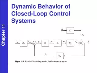
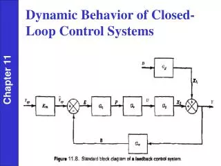
Control System Instrumentation Chapter 9 Figure 9.3 A typical process transducer. Transducers and Transmitters • Figure 9.3 illustrates the general configuration of a measurement transducer; it typically consists of a sensing element combined with a driving element (transmitter).
Since about 1960, electronic instrumentation has come into widespread use. Sensors The book briefly discusses commonly used sensors for the most important process variables. (See text.) Transmitters Chapter 9 • A transmitter usually converts the sensor output to a signal level appropriate for input to a controller, such as 4 to 20 mA. • Transmitters are generally designed to be direct acting. • In addition, most commercial transmitters have an adjustable input range (or span). • For example, a temperature transmitter might be adjusted so that the input range of a platinum resistance element (the sensor) is 50 to 150 °C.
Instrument Selection Criteria • solid/gas/liquid, corrosive fluid • nature of signal, speed of response • accuracy, measurement range • costs • previous plant practice • available space • maintenance, reliability • materials of construction • invasive/non-invasive • environmental/safety (enclosures, fugitive emissions) Chapter 9
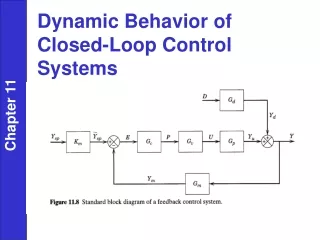
Transmitter/Controller Chapter 9 May need additional transducers for Gm if its output is in mA or psi. In the above case, Gc is dimensionless (volts/volts).
Chapter 9 Figure 9.15 Nonideal instrument behavior: (a) hysteresis, (b) deadband.
Measurement / Transmission Lags • Temperature sensor • make as small as possible (location, materials for thermowell) • Pneumatic transmission lines • usually pure time delay, measure experimentally (no time delays for electronic lines); less common today compared to electronic transmissions. Chapter 9
Three valve characteristics determined by plug shape: (1) Quick Opening (square root trim) (2) Linear Trim (3) Equal Percentage must take other flow obstructions into account for actual valve performance Chapter 9
Chapter 9 See Example 9.2
Suppose valve has linear trim and flow must be changed. If p through exchanger does not change, valve would behave linearly (true for low flow rates), since it takes most of p . For lower flow rates, p through exchanger will be reduced, changing effective valve characteristics (valve must close more than expected nonlinear behavior). Equal % in this case behaves more like linear valve. Size pvalve = 25% total p , at s=50% (Δp→$) valves need to operate between 5% and 95%, Chapter 9
Failure philosophy: Keep process pressure low, protect environment (equipment and engineers) Pneumatic control valves are to be specified for the applications listed below. State whether an A-O or A-C valve should be specified for the following manipulated variables: (a) Steam pressure in a reactor heating coil. (b) Flow rate of reactants into a polymerization reactor. (c) Flow of effluent from a wastewater treatment holding tank into a river. (d) Flow of cooling water to a distillation condenser. Chapter 9
Chapter 9 Previous chapter Next chapter