Download
1 / 68
691 likes | 970 Views
Multiplexing/MAC. Malathi Veeraraghavan Univ. of Virginia. Outline Types of links Multi-access (shared single) link Point-to-point link Types of multiplexing techniques Circuit-based multiplexing Packet-based multiplexing. Purpose of multiplexing/MAC. To share link bandwidth. MAC.

E N D
Multiplexing/MAC Malathi Veeraraghavan Univ. of Virginia • Outline • Types of links • Multi-access (shared single) link • Point-to-point link • Types of multiplexing techniques • Circuit-based multiplexing • Packet-based multiplexing
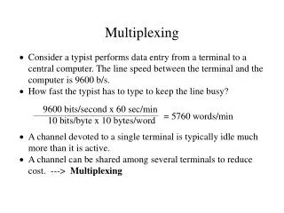
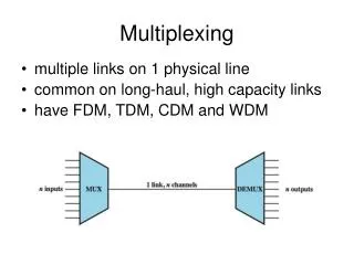
Purpose of multiplexing/MAC • To share link bandwidth
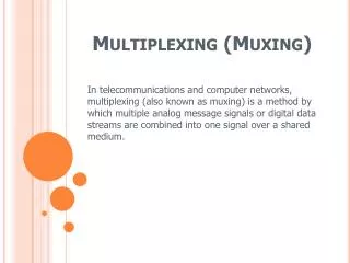
MAC • MAC: Medium Access Control or Media Access Control • Set of functions to support the sharing of a single link by multiple endpoints • MAC vs. Multiplexing (MUX) • The term "MAC" is used to describe sharing techniques on multi-access links • The term "multiplexing" is used to describe sharing techniques on point-to-point links
Types of links • Multi-access links • Typically used to connect multiple hosts to a switch • Cheaper than point-to-point links • Mostly used in wireless networks • Sometimes in wired networks through hub • Point-to-point links • Typically used between switches • Increasingly typical between hosts and switches in wired networks (port costs are decreasing) Switch ...... Host Host Host Host Switch Host Host
Analogy of a MULTI-ACCESS LINK - several driveways attached to one road Courtesy: http://mars.gmu.edu/dspace/bitstream/1920/2497/1/pca_608_23_16n.jpg
Recall our multiple-link network shared using MUX techniques Point-to-point link Point-to-point link Switch Host Host Switch Switch Host Host e.g., roadways network (an intersection is comparable to a switch)
Multi-access wireless link between hosts and switch Multi-access wireless link Host Switch Host Switch Switch 802.11 wireless access point Host Host Switch Equivalent to: ...... Host Host Host Image courtesy: http://compnetworking.about.com
Multi-access wireless link(cell phones) Base station/cell site Switch Switch Switch Images courtesy of cnet.com and wikipedia
Multi-access wired link between hosts and switch Multi-access wired link Host Switch Host Switch Switch Ethernet hub Host Host Recall a hub is a multipoint repeater from tasks/layers class notes: shared single-link network Image courtesy: wikipedia
Usage of links • Point-to-point links • Host-to-switch, or more generally endpoint-to-switch (e.g., telephone, video camera) • Switch-to-switch • Multi-access links • Endpoint-to-switch
Back to outline (status check) • Outline • Types of links • Multi-access link • Point-to-point link • Types of multiplexing techniques • Circuit-based multiplexing • Packet-based multiplexing
Classification of Multiplexing/MAC techniques Multiplexing/MAC techniques Circuit-based multiplexing Packet-based multiplexing • Position based: • space • time • frequency • Each multiplexed data stream occupies a different position • Packet header based: • header carries destination address • Each multiplexed data stream consists of packets with headers carrying corresponding destination addresses
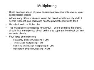
Circuit-based multiplexing • Frequency Division Multiplexing (FDM) • Called Wavelength Division Multiplexing (WDM) in the optical range • Time Division Multiplexing (TDM) • Space Division Multiplexing (SDM) • Each fiber in a fiber bundle
Frequency Division Multiplexing Signal 1 (c) The multiplexed signal Signal 2 Signal 3 Signal 1 Signal 2 Signal 3 (a) The original signals (b) The signals modulated on to different carrier frequencies Tanenbaum
Frequency Division Multiplexing (FDM) • Each communication session is assigned its own frequency for the session • A few control channels (frequencies) are set aside to allow users to send requests for frequencies for their communication sessions (these requests are called "call setup signaling protocol messages") • Frequencies are released upon completion of the session (with "call release signaling protocol messages") • Modulation technique determines the required carrier spacing (e.g., 30 kHz for analog cellular) and correspondingly the number of simultaneous sessions • Examples • Each broadcast radio and TV station is assigned a different carrier frequency – long-held “sessions” • Analog cellular systems: two frequencies are assigned – one for reception, another for transmission to each cellular caller
Time Division Multiplexing (TDM) • Each communication session is assigned time slots for its session on one or more frequencies • A few control channels (time slots) are set aside to allow users to use for signaling messages, i.e., to send requests for timeslots for their communication sessions • Timeslots are released upon completion of the session • Examples • Classroom being shared by multiple classes one after another in time • Digital cellular systems: US system has three users sharing one carrier frequency for a cellular call
Frequency and time:many practical systems are hybrid Carrier Hybrid FDM/TDM FDM TDM Frequency Frequency Frequency Time Time Time Basic principle ofcommunication: Two regions in the time-frequency plane with equal areas can carry the same amount of information
Use of circuit-based multiplexing on different types of links • Multi-access wireless link • Cellular phones • Point-to-point links between switches
Use of FDM and TDM techniques on a multi-access link • FDM sharing on a multi-access link is referred to as FDMA (Frequency Division Multiple Access) • TDM sharing on a multi-access link is referred to as TDMA (Time Division Multiple Access)
Forward and reverse channels Reverse channels Switch Switch Switch Forward channels Base station/cell site Images courtesy of cnet.com, wikipedia, google
Example of FDMA scheme:Advanced Mobile Phone System (AMPS) • FDMA/FDD • Spectrum allocation by FCC: A and B allocations to different providers Reverse Forward A Original B A B 825 845 870 890 A A B A B A A B A B Extended 824 825 845 849 869 870 890 894 20 MHz is the width of the allocated band: 845-825 and 890-870 30 kHz is the per-channel bandwidth required for an AMPS phone call
Duplex techniques • Separates signals transmitted by base stations from signals transmitted by terminals • Frequency Division Duplex (FDD): use separate sets of frequencies for forward and reverse channels (upstream and downstream) • Time Division Duplex (TDD): same frequencies used in the two directions, but different time slots
Dimension of space • Reuse the frequencies used at a cell C at another cell D that is far enough from C
Hexagonal cell frequency plan • D: Distance between a base station and the nearest base station that uses the same channels • R: Radius of a cell • Reuse distance = D/R • Channel plan: method of assigning channels to cells to guarantee a minimum reuse distance between cells that use the same channel • S/I: Signal to Interference Ratio D R which is the minimum reuse distance for which
Reuse factor(frequencies are reused every N cells) • Divide the set of available channels into N groups • N: reuse factor; select N such that cells assigned the same frequencies will have a D:R ratio greater than (D:R)req • For hexagons, reuse factor N is given by • Practical values of N • range from 3 to 21 • most commonly used: 7 (D/R = 4.6)
Service provider A • Has a total of 832/2 = 416 channels • Set aside 21 for control channels for each provider • Therefore 416-21 = 395 traffic channels per provider • Per cell, we can have 56 and 3/7 channels if N=7 • Four cells are given 56 channels and three cells are given 57 channels
Practice: IS136 NA-TDMA • NA-TDMA is a hybrid FDMA/TDMA scheme • Therefore each frequency will have time slots that are shared by multiple calls • Typical: three calls share one frequency • NA-TDMA is three times as efficient • Same frequency allocation as for AMPS • Carriers are 30 kHz apart - Bandwidth
6 1 2 3 4 5 6 1 2 3 4 6 1 2 3 4 5 6 1 2 3 4 5 The TDMA aspect: frames and time slots • Every frame is 40ms long and consists of 6 time slots base station to mobile 45 MHz or 80 MHz mobile to base station 40ms
What data (transmission) rate can be used at each carrier frequency? • Each time slot carries 324 bits • There are 6 timeslots/frame • 1 frame is 40ms • Therefore, data rate per carrier (frequency) is:
Data rate of a carrier (frequency) • Voice calls in NA-TDMA • Speech codec rate: 7.95kbps • Channel coding rate: 13kbps • Fits within 16.2kbps • One voice call needs two timeslots per frame • So three calls can be carried at each carrier frequency
Use of circuit-based multiplexing on different types of links • Multi-access wireless link • Cellular phones • Point-to-point links between switches
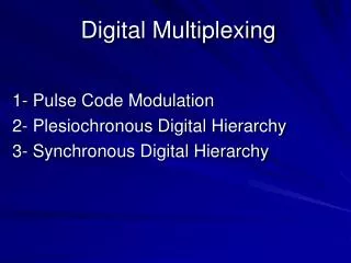
Techniques used in practice today • Time-division multiplexing • Plesiochronous Digital Hierarchy (PDH) • DS0, DS1, DS3 (one phone call: DS0) • Synchronous Optical Network (SONET) - US • Synchronous Digital Hierarchy (SDH) - others • Wavelength-division multiplexing (on fiber)
Time Division Multiplexing: The T1 carrier (1.544 Mbps) Input links Output link 1 2 . . 2 1 24 24 ........... 8 bits every 125s RATE: ? 8 * 24 + 1 = 193 bits every 125s RATE: ? Round-robin cycle through and transmit 8 bits each from input 1 through 24 onto output link and then start again from input 1
North American Digital Multiplexing Hierarchy • DS0, 64 kbps channel • DS1, 1.544 Mbps channel (T1) • DS2, 6.312 Mbps channel • DS3, 44.736 Mbps channel (T3) • DS4, 274.176 Mbps channel 1 DS1 signal, 1.544Mbps Mux 24 1 DS2 signal, 6.312Mbps 24 DS0 4 DS1 Mux 4 1 DS3 signal, 44.736Mpbs 7 DS2 Mux 7 1 6 DS3 Mux 6 DS4 signal 274.176Mbps
Synchronous Transport Signal (STS-1) Frame 90 columns 90 x 9 = 810 bytes Byte Byte 810 x 8 bits/125 sec = 51.84Mbps STS-1 rate = 51.84Mbps 1 User Data Order of transmission 2 9 rows SPE is 87 columns Frame period = 125 sec Overhead (3 columns): error detection bits, etc. Line overhead + Section overhead Payload called Synchronous Payload Envelope (SPE) Path overhead: one column inside SPE
SONET/SDH rates(number is the multiplier) Optical Carrier How many bits are carried within a single SONET frame of an OC48 signal? How many bits of the above number can be used to carry user data (payload)? Verify that the SPE data rate in the table above is correct for the OC48 signal. Tanenbaum
Back to outline (status check) • Outline • Types of links • Multi-access link • Point-to-point link • Types of multiplexing techniques • Circuit-based multiplexing • Packet-based multiplexing
Packet-based multiplexing • For point-to-point links • Scheduling techniques • For multi-access links • Random access MAC schemes
Packet-based multiplexing on a point-to-point link Scheduling algorithms: FCFS, priority Header Data payload A Packet-based multiplexer B Output link C Input links Packet: a string of bits Payload: user-data bits being sent Header: overhead added by protocol
Packet buffering • Buffers hold packets waiting to be transmitted on output link • FCFS: Single buffer • Priority: As many buffers as there are priority classes • When the transmitter is ready to choose the next packet for transmission • FCFS: Select next packet in line if buffer is non-empty • Priority: Check buffers in order of priority and transmit packet from the first non-empty buffer
Rules for order of packet transmission • If a packet P arrives when the transmitter is free, and all buffers are empty, then the packet will be transmitted immediately. Add packet transmission time to packet arrival time to determine packet departure time. • If a packet P arrives into a buffer while another packet Q is being transmitted, packet P is served only after • Packet Q is fully transmitted (non-preemption), and • Higher-or-equal priority packets that are already in the buffers are transmitted. • Based on scheduling discipline, and the number of packets ahead of packet P in the buffers, determine departure time for P.
Examples of packet multiplexing • Point-to-point links between switches • Point-to-point link between endpoint and switch
Packet-based multiplexing on a point-to-point link between switches Switch Host 2 Host 1 Switch input link output link Packet-based multiplexer Host 3 input link Host 4
Packet-based multiplexing on a point-to-point link between switches Switch Host 2 Host 1 App. 2 App. 2 Switch Host 3 Host 4 App. 1 App. 1 Two communication sessions sharing this switch-to-switch link
Packet-based multiplexing on a point-to-point link between a host and a switch Packet-based multiplexer Host 1 App. 2 Host 2 App. 3 App. 2 Switch Switch Host 3 Host 4 App. 3
Packet-based multiplexing on a point-to-point link between a host and a switch Host 1 App. 2 Host 2 App. 3 App. 2 Switch Host 3 Host 4 App. 3 Two communications sessions sharing this host-to-switch link
Back to outline (status check) • Outline • Types of links • Multi-access link • Point-to-point link • Types of multiplexing techniques • Circuit-based multiplexing • Packet-based multiplexing • For point-to-point links • Scheduling techniques • For multi-access links • - Random access schemes
Random access MAC protocols • No reservations are made; instead a host just sends data packets • What can happen? • Collision (recall multi-access) • Need to avoid collisions or detect collisions and retransmit • What’s the cost of being too careful to avoid collisions? • Utilization will be sacrificed
Analogy of a MULTI-ACCESS LINK: a car pulls up to a road; driver looks right/left before entering - called "carrier sensing" Courtesy: http://mars.gmu.edu/dspace/bitstream/1920/2497/1/pca_608_23_16n.jpg