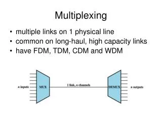
Multiplexing
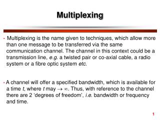
Multiplexing. MULTIPLEXING. Multiplexing. "sharing” fasilitas komunikasi. Penggunaan satu fasilitas komunikasi (spt saluran transmisi) oleh beberapa user. multiplexing…. 1. Space Division Multiplex (SDM)


Multiplexing
E N D
Presentation Transcript
MULTIPLEXING Multiplexing "sharing” fasilitas komunikasi Penggunaan satu fasilitas komunikasi (spt saluran transmisi) oleh beberapa user
multiplexing… • 1. Space Division Multiplex (SDM) • Skema “original” memisahkan sinyal untuk transmisi dan switching — contoh, analog telephone switching office crossbar menyambungkan saluran telpon yang terpisah dengan wiring matrix • Fasilitas didefinisikan sbg communication link akan tetapi bisa juga didef. sbg pole line atau kabel pada SDM. • Contoh SDM dapat dilihat pada hal berikut :
Contoh SPACE DIVISION MULTIPLEXING 2. Sharing same radio channels and cable routes via separate rights of way 1. Sharing a “pole line” via separate open wire transmission paths 3. Sharing same radio channels via different satellite footprints
4. Cellular telephone reuses same channels in non-adjacent cells. The smaller the cells, the more participants per space can operate in a region.
2. Frequency Division Multiplexing (FDM) • Concept is of using sine waves as carriers • Each carrier is modulated by a different signal using AM, FM, PM, or combinations of AM and FM or AM and PM, such as QAM • Modulation schemes by their nature produce energy within separate spectral ranges either centered on or near the frequencies of each carrier frequency • Band pass filters are used to separate out each modulated signal • Detection schemes are used to regenerate each individual signal
No Channel 1 Little gap 4-5 Biggap 6-7 Huge gap 13-14 Going 54 - 59 Going 60 - 64 Gone 64-68
US (NTSC) TELEVISION BROADCAST SPECTRUM Luminance (brightness contours), two colorado difference signals (hue and saturation), and various sound signals are combined within each 6 MHz channel
Wavelength Division Multiplexing (WDM) is a FDM scheme used in optical communications where various wavelengths of infrared light are combined over strands of fiber. Each wavelength is amplitude modulated by a digital bit stream (usually NRZ encoded, i.e. on/off pulses of light) so that as many as eighty 50 GHz wide channels can be combined on each 5 micron diameter strand of glass in the case of D (for dense) WDM. Of course, WDM is FDM. Wavelength is c/f, but frequencies are in the THz range for "light.“ Optical communications with few exceptions are digital since light transmitters and receivers are usually poorly suited for analog modulation.
3. Time Division Multiplexing– four basic concepts • LANs: Not discussed in this chapter is the contentious use of a shared facility by many sources and destinations where no intervening multiplexer devices are used. Instead, a peer to peer access scheme is built into each device attached to the shared facility. This is the basis of Local Area Networks and Metropolitan Area Networks, and in a most general (but not necessarily in a specific sense) the Internet. We will discuss LANs, MANs, and WANs later in the course and in future courses. • CIRCUIT SWITCHING: The facility--communications link--is seized by one user for the length of communications session. Such circuit switched schemes dedicate the entire path until the entire message is completed. This is the concept behind telephone trunks or party lines. That is, the transmission path is dedicated until session is ended. Everyone else has to wait or take another path if available. • PACKET SWITCHING: The facility is shared for one packet at a time (packet switched) by many users. The route the packet takes is either dedicated or can be dynamic. This is the basis of X.25 and ATM circuit switched networks and the Internet “backbone”. • PAM, PCM, etc.: Individual frames or even down to individual coded samples are interspersed in “time slots” on single communications links. This is the basis of TDM multiplexers studied in Stallings Chapter 8.
Time Division Multiplexers Synchronous & Statistical Mux’s • Stallings doesn't mention the essentially analog technique of interspersing analog samples from multiple analog signal sources into a stream of amplitude modulated pulses on a single analog link and separating these samples from each other to reconstruct the originals. There is no quantizing or digital conversion. This “Pulse Amplitude Modulation” (PAM) scheme was widely used in telephone switching offices and PBXs into the 1970s and later. • The TDM methods we will discuss in some length in Data Communications 1 from Chapter 8 of the text involves combining digital signals from various sources over a single link. • The original uses of TDM mux’s was to allow low data rate multiple “terminals” to share coaxial or twisted pair transmission paths • Terminals did not necessarily generate full time data • Control schemes define the two basic types of mux’s
Time Division Multiplexers • The topic of Stallings Chapter 8 is specifically dedicated to discussing those devices inserted between end points to control and format the sharing of signals • These specific devices are called "Multiplexers” • You will also hear the jargon term "mux“ referring to both synchronous and statistical multiplexers • The original use for “mux’s” was for many terminals to share a communications link more efficiently. • Synchronous mux’s provide dedicated time slots for each source and minimal overhead and latency • Stat mux’s share time slots as needed instead of permanently assigning them to individual terminals. • In both kinds of mux’s, time slots are assigned to digital representations of individual samples or frames of each signal source in a rotating manner
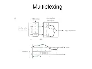
TDM MULTIPLEXERS : • A. Synchronous Multiplexers • Each device is assigned a time slot in a fixed rotating manner • Assigned time slots are unused when device is not active • Latency is low since there is no processing other than delay for placing sample into appropriate slot and recovering it • Identification of user is by physical connection or equivalent • Pulse Stuffing is necessary to account for (slightly) different clocking of sources • The concept is fully developed in T-carrier systems and SONET which are good examples to study
T-1 SCHEME BASICS • Sample each of 24 3,000 Hz voice telephone lines at 8000 samples/second • Binary encode samples at 128 levels, either linear or non-linear quantizing. Digital bit stream for each signal is called a “DS-Ø” thus providing 7 bits per sample • Use an 8th bit per source channel for signaling and supervision and to ensure that “one’s density” is sufficient for receiver to regenerate clock signal • D-4 “Super Frame” T-1 uses a framing word to ensure receiver can identify location of each sample in digital stream. The framing word in interspersed into data one bit at a time after each set of 24 signals are sent (every 193 bits in the data stream) and retrieved via a cleaver correlation technique invented 50 years ago! • In “Extended Super Frame” T-1 some of the framing word’s bits can be used alternatively for other purposes such as a CRC calculation and an additional low rate data link which is usually used for maintenance purposes • T-1 uses the AMI encoding format over 4-wire twisted pairs with roughly one mile (“6 kft”) spacing between repeaters. • AMI polarity violations can be used to free up 8th bit when data is sent through so “clear channel” schemes (e.g. B8ZS) which use bit substitution similar to that used for HDLC flags but in this case to prevent too many zeros in a row.
T-Carrier hierarchy • Definition: DS-x is data rate and T-x is scheme • Much involved combining of “T-carriers” into higher data rate systems • Difficult to separate out individual channels other than with basic T-1 requiring a “Digital Access and Cross-Connect System” (DACS)
SONET and SONET hierarchy • Optical fiber based system • Starts at basic 51.84 Mbps rate called OC-1 with OC-n multiples of that rate • Much simpler than T-carrier for separating out individual OC channels
B. Statistical Multiplexer Basics • More attached devices than time slots • Dynamic assignment of time slots based on need with numerous possible schemes of deciding how to do this • Identification of device connections (called, “tail circuits”) needs to be added to data since slot allocations are not permanent. Implies additional overhead bits. This adds overhead bits • Originally for many dumb terminals—with low occupancy—to communicate with main frames. • Now used for Cable Modems which has a similar characteristic. • Usually all devices can not be sending simultaneously for any length of time • The Service Ratio defines potential aggregate data rate need versus actual capacity of communications link. This can be large number for dumb terminals • Stat mux schemes can employ data buffers to handle bursts of more data being generated than can be put on communication channel • New data can not be handled when buffers fill • Latency is an issue since individual users may have to wait for available time slot(s) directly or for the buffers to be emptied
Contoh MULTIPLEXING • STAT MUX: CABLE MODEMS (DOCSIS) • FDM: xDSL • TDM: TOKEN RING AND ARCNET LOCAL AREA NETWORKS (peer to peer controlled time slot schemes) • TDM: EITHERNET LOCAL AREA NETWORK (peers contend for access to send packets) • FDM and TDM: IEEE 802.11 WIRELESS LANS • FDM, TDM, SPREAD SPECTRUM: CELLULAR AND CORDLESS TELEPHONES (channelized FDM, TDMA, Frequency Hopping Spread Spectrum, Direct Sequence Spread Spectrum, CDMA) • You will get the chance to study all of these. Let’s look at a few interesting ones now…
Perbandingan modem DOCSIS-1 • DOCSIS-2 and other systems to provide much greater data rates • DOSCIS systems are usually “asymmetrical” • Transmission encoding is 64-QAM, 128-QAM, or 256-QAM
DIGITAL SUBSCRIBER LINKS (xDSL) • Uses Discrete Multi-tone (DMT) with 4 kHz spacing • Each “tone” uses QAM • Can be “symmetrical” or “asymmetrical” • Data rates up to multiple Mbps per twisted pair lines plus traditional telephone
4. A Time Division Multiplex Variation TIME DIVISION MULTIPLE ACCESS (TDMA) TDMA is really just a kind of STATISTICAL multiplexing used for cell phones. Channels are assigned for individual calls and reassigned as users moves between cells. The American cellular TDMA networks and American and international GSM networks use variations of TDMA.
5. Some Frequency Division Multiplex Variations ORTHOGONAL FREQUENCY DIVISION MULTIPLEXING OFDM is a newer encoding scheme used in IEEE 802.11a and IEEE 802.11g wireless LANs. 802.11a incorporating 8 non-overlapping 20 MHz channels where each channel is divided in 52 sub carriers, each approximately 300 KHz wide. 802.11g is similar but shares channel with 802.11b. This is “straight” channel based WDM but like the next one, the use of each channel is interesting. CODED ORTHOGONAL FREQUENCY DIVISION MULTIPLEXING COFDM fills the transmission channel with 2,000 or even 8,000 carriers (raw value, actual number of carriers is less), each modulated by QPSK, 16-QAM, or 64-QAM used for digital TV broadcasting but not in the US which uses 8-VSB, a 3 bit/baud digital version of analog TV broadcasting.
6. A Horse of a Different Color CODE DIVISION MULTIPLE ACCESS (CDMA) CDMA is a time correlation scheme which does not use the time slot method of TDM to combine and retrieve signals. Instead digital code words are used to spread each bit into a higher bit rate unique pattern. The signals combined by this method can be separated by the receivers using the same code word used to encode each signal. We will address CDMA as part of our upcoming study of SPREAD SPECTRUM.