Download
1 / 61
610 likes | 879 Views
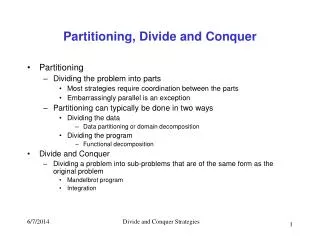
Case Study: “Hardware/Software Partitioning to Meet Real-time Constraints”. EECE 579 Advanced Topics in VLSI Spring 2009 Brad Quinton. Overview of this Slide Set. Look at a real-world, real-time design problem. Partition the implementation between software and hardware.

E N D
Case Study: “Hardware/Software Partitioning to Meet Real-time Constraints” EECE 579 Advanced Topics in VLSI Spring 2009 Brad Quinton
Overview of this Slide Set • Look at a real-world, real-time design problem. • Partition the implementation between software and hardware. • Design a simple hardware/software interface to support this partition.
SONET Automatic Protection Switching (APS) • SONET (Synchronous Optical Networking): • The North American standard for optical networking • The vast majority of current optical networks use this standard • Designed to be tightly synchronized and highly reliable • Defined in standard ANSI T1-105 • Automatic Protection Switching (APS): • Ensures network reliability by switching an errored channel to a backup channel • Requires real-time error monitoring and switching
High Level System View Requirement: If the Bit Error Rate of any given working STS-1 channel exceeds 4 errored frames in a 10-frame sliding window, the egress channel must switch to the protection STS-1 within 300 s.* * Note: This is a simplified version of the true requirement.
SONET Format Overview STS-1 (OC-1) Frame: * From : Fiber-Optic and Satellite Communication, Gilbert Held, http://www.microsoftt.com/technet/itsolutions/network/evaluate/technol/fiberop.mspx
SONET Format Overview STS-1 (OC-1) Frame: Parity Byte * From : Fiber-Optic and Satellite Communication, Gilbert Held, http://www.microsoftt.com/technet/itsolutions/network/evaluate/technol/fiberop.mspx
SONET Multiplexing • The SONET standard supports multiple bit rates by multiplexing the basic STS-1 channels together. • Our design is targeted at STS-192 (OC-192), therefore we will have 192 independent STS-1 channels to manage. • The basic STS-1 line rate is 51.48 Mbits/s, therefore our STS-192 stream will have a line rate of 9.953 Gbit/s.
SONET Multiplexing 51.48 Mb/s 9953 Mb/s
SONET Multiplexing 51.48 Mb/s • Stream is transmitted serially • STS-1 channels are interleaved on a “byte-by-byte” basis 9953 Mb/s
Parity Checking • Parity checking is simple way to detect bit errors. • Parity can be calculated on a single byte: For example, we could add a bit to ensure that there are always an even number of 1s in a 9 bit segment: • Notice that if one of the data bits is changed the parity will be incorrect and we will know that we have an error.
Parity Checking • Since optical networking tends to have low bit error rates, it is not worth transmitting an extra bit with every byte of data. • There are a number of ways that this idea can be extended protect an entire frame. • For example, a single byte can cover any number of proceeding bytes as follows: Calculate parity for each bit position in a byte.
SONET Format Overview STS-1 (OC-1) Frame: Parity Byte * From : Fiber-Optic and Satellite Communication, Gilbert Held, http://www.microsoftt.com/technet/itsolutions/network/evaluate/technol/fiberop.mspx
Design Problem Summary • In order to ensure that reliable communications are maintained in the optical network we will implement automatic protection switching (APS) by doing the following: • Calculate the running parity of each independent STS-1 channel. • Check the calculated parity of the each individual STS-1 frame against the parity byte included in the frame overhead. • Record bit errors indicated by mismatched parity on a STS-1 basis. • If the number of frame with bit errors exceeds 4 per 10 frames change the switch settings to use the protection channel.
Basic Switch Design • The basic design does not support automatic protection switching: • => We are going to add APS to the design.
Initial “back-of-the-envelope” Partitioning • In general, when approaching any new design, it is worthwhile to step back a little bit, and do some “back-of-the-envelope”-type analysis • This can save a lot of time by eliminating infeasible designs and helping you understand what the will be important in the final design • There are many ways to do this. The goal is to use basic information that you already know, before running off to do complex analysis of the problem. • One way: • Propose simplest (or cheapest) solution, then try to figure out why it won’t work.
Idea 1: All-Software Solution • Can we implement this design in software running on the processor that we already have in our design?
Idea 1: All-Software Solution • What do we know at this point: • The line rate is 9.953 Gb/s => There will be a new byte of data for processing at a rate of 1.244 GHz • The latest Intel processors run at ~2.5 GHz => in the best case (no overhead, stalling, etc) we could execute 1 instruction per clock cycle) • Analysis: • Even using the fastest high-end processor, and assuming very optimistic conditions would have only 2 instructions to process each data byte • Conclusion: • There is no way to achieve an all-software solution
Idea 2: All-Hardware Solution • Since the all-software solution is not going to work, can we implement this design completely in hardware?
Idea 2: All-Hardware Solution • What do we know at this point: • The software for the operator interface was already been written • The switch hardware already exists • Management always wants the cheapest solution that is also low-risk and provides the fastest possible time-to-market • Analysis: • Re-implementing existing work is risky, expensive and slow. We are likely risking our careers if we decide to re-implement a large amount of existing software in hardware • Conclusion: • An all hardware solution is not a good idea
Initial “back-of-the-envelope” Results • The more experience you gain as a designer, the further you will be able to go with this kind of quick analysis. • For this example, we will stop here with the conclusion: • Given the design real-time design requirements and the existing design components, the design will require a combination of hardware and software.
Design Planning • Once you have done all you can based on your current experience, you must research the specifics of the design and the target platform • You need to find out all the relevant performance details about the platform you are working with so that you can evaluate the different hardware/software partitions • This can be a lot of work. Real-life systems are very complicated, and there are a lot of variables to think about. • For this example we are lucky, since we are provided with a (simplified) version of the real information.
Processor Specifics Basic embedded processor: • - 200 MHz clock frequency • - 25% of clock cycles are available for APS (other clock cycles are used for OS, Crossbar Switch, etc.) • DRAM memory access require 100 ns • Interrupt service routine requires 1600 ns
Processor/Hardware Interface Simple generic processor interface: • data width:16 bits • address width: 16 bits • read cycle time: 50 ns • write cycle time: 50 ns
Processor/Hardware Interface Simple generic processor interface: • data width:16 bits • address width: 16 bits • read cycle time: 50 ns • write cycle time: 50 ns System bus
Hardware Specifics Our New Hardware Design: • System clock rate: 622 MHz • Analog serial Rx/Tx provides 2 bytes/clock (1.244 bytes/second)
Partitioning • Now that we know all the basic performance of elements in the systems we can start partitioning our design. • Basic procedure: • Determine a potential hardware/software partition of the design functionality. • Determine the worst-case performance of the system using this design. • Determine if this performance meets the design requirement. • Continue to try new partitions until the system meets the design requirement.
Initial Partition • First, lets enumerate the basic design functionality:
Initial Partition • Now, assign each function to hardware or software:
Evaluation of Hardware/Software Partition • There are number of ways to evaluate the performance of a hardware/software partition: • Implement the Design - Basically, try it out and see if it works. (This is most straight forward method, but it is risky.) • Model the Design Components - Build software models of all the system and then simulate to determine the worst-case performance. (This removes the risk of creating a design that doesn’t work, but creating models is a lot of work.) • Manually Calculate Performance - Identify the key performance characteristics of each part of the design and manually determine the worst-case performance. (This works for small designs, but can quickly become too complicated in real systems)
Evaluation of Hardware/Software Partition • For this example, we will manually evaluate the worst-case performance. • First, we need to identify the worst-case condition:
Evaluation of Hardware/Software Partition • For this example, we will manually evaluate the worst-case performance. • First, we need to identify the worst-case condition: • Each of the 192 STS-1s crosses the 4/10 errored frame threshold at the same time, and requires protection switching
1) Calculate parity for each new byte Our hardware system clock is 622 MHz and we receive 2 bytes of data every clock cycle. If we design two parity calculation blocks that run it parallel we will be able to maintain the line rate. --> 1 clock cycle = 1.6ns, no problem….
2) Compare the current parity versus parity byte We must compare the current running parity for each STS-1 versus the parity byte in the frame overhead, once per frame, In the worst case we will have to check two parity bytes at the same time, so we need two parity compare circuit running in parallel. --> 2 clock cycles = 3.2 ns, Good….
3) Track errors/frame for each STS-1 In the worst case the each of the 192 STS-1 streams will contain a bit error on the same frame. The hardware must communicate this information to the software. We have two choices for the interface: Interrupts - Each parity byte mis-match causes an interrupt to the processor Polling - The processor continually reads information from the hardware to determine if there is an error Interrupts: 192 interrupts * 1600 ns/interrupt = 307200ns = 307.2s > 300 s APS switch requirement --> won’t work
3) Track errors/frame for each STS-1 Polling: We must be able to read the status of every STS-1, on every frame time. The frame time is: 9 * 90 bytes = 810 bytes per frame (1/51.48 Mb/s) * 8 bits/byte = 155.4ns/byte 810 bytes/frame * 155.4ns/byte = 125874ns/ frame Read access time is: 50 ns/ 16 bit read * 12 reads = 600ns <--- works! Solution: Hardware will maintain 12, 16-bit words which represent the error status for each of the 192 STS-1 streams. The software will poll each of these words once per fame time to determine the status of the STS-1.
Interrupts vs. Polling SIDENOTE: This part of the example provides a good example of a trade-off that often occurs when partitioning design problems between hardware and software. In general, events occur in the hardware that must be communicated to the software portion of the system. There are two methods to handle this: The hardware can alert the software asynchronously using an interrupt. The software can periodically check the status of the hardware and determine what has changed.
Interrupts vs. Polling The decision of which method to use is very important from a real-time design point of view. Interrupts: Provide the fastest possible indication of an event, and therefore potentially allow for very fast reactions, however because they are asynchronous, a large number of interrupts can happen at once, and the worst-case performance may be poor. Polling: Allows for very predictable performance, however the reaction to given event is slower since the worse-case it is dictated by the period of the polling. Also, polling can be quite inefficient if the events happened very rarely. Because of this, real systems often use a combination of polling and in interrupts. As well, the interrupts are often grouped into hierarchies and categorized with different priorities.
4) Check the 4/10 threshold on each STS-1 The “sliding window” requirement makes this calculation a little bit less straight forward. One way to manage this is to store the STS-1 parity errors as bits in the least significant 10 bits of a 16-bit word. Each of the 10 bits represents a STS-1 frame that we have evaluated. ‘1’ indicates an errored frame, ‘0’ indicates a clean frame. For example: STS-1 Sliding Window Error Tracking Frame error Correct Frame If there is ever > 4, ‘1’ in the 10 LSBs then the threshold is exceeded
4) Check the 4/10 threshold on each STS-1 for (i := 1 to 192) { // manage status current = status[i]; current << 1; if (error[i]) current = current | 0x0001; status[i] = current; // determine threshold sum = 0; for (j := 1 to 10) { tmp = current & 0x0001; sum = sum + tmp; current >> 1; } if (sum > 4) switch[i] = 1; else switch[i] = 0; } 4 instructions + 2 DRAM accesses 10 * 3 instructions 1 instructions + 1 DRAM access
4) Check the 4/10 threshold on each STS-1 • calculate time to check all 192 thresholds: • total_time • = 192 * ( 35 instructions + 3 DRAM accesses) • = 192 * ((35 * 5 ns) + (3 * 100 ns)) • = 91200 ns • = 91.2 us
5) Update Protection Switch Settings • This is function is easy to implement since the software for the switch settings is already implemented on the same processor. Any message passing system will work. • We will use an array ‘switch’ stored in memory: • 192 * DRAM access = 192 * 100 ns = 19200 ns = 19.2 us • In order to update the switch settings the software must make a worst case of 192 / 16 = 12 write accesses: • 12 writes * 50 ns/write = 600 ns
6) Alert Operator to Switch Status Again, this is function is easy to implement since the software for the switch settings implemented on the same processor. Also, there is no hard real-time constraint on this function. We will simply pass a message to the display software, and assume that it will be displayed eventually….
Overall Worst Case Timing Therefore our worst case time to perform an APS switch is….
Overall Worst Case Timing Therefore our worst case time to perform an APS switch is…. Total: 111.6 us
Processor Utilization • We have designed a partition that will meet the real-time requirement, but we were also constrained to use only 25% of the processor clock cycles, so we need to check this as well: • Frame time = 125874 ns = 125.9 us • APS Software = 111.6 us / frame • Therefore, the APS Software requires 88.64% of the resources! • This is a problem. Our partition does not meet the design requirements.