Download

1 / 11
110 likes | 276 Views
American Meteorological Society Seventh Conference on Polar Meteorology and Oceanography and Joint Symposium on High-Latitude Climate Variations. Paper 3.12. TURBULENCE DECAY IN THE STABLE ARCTIC BOUNDARY LAYER. Andrey A. Grachev

E N D
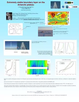
American Meteorological Society Seventh Conference on Polar Meteorology and Oceanography and Joint Symposium on High-Latitude Climate Variations Paper 3.12 TURBULENCE DECAY IN THE STABLE ARCTIC BOUNDARY LAYER Andrey A. Grachev University of Colorado CIRES / NOAA Environmental Technology Laboratory, Boulder, Colorado Christopher W. Fairall NOAA Environmental Technology Laboratory, Boulder, Colorado P. Ola G. Persson University of Colorado CIRES / NOAA Environmental Technology Laboratory, Boulder, Colorado Edgar L Andreas U.S. Army Cold Regions Research and Engineering Laboratory, Hanover, New Hampshire Peter S. Guest Naval Postgraduate School, Monterey, California Rachel E. Jordan U.S. Army Cold Regions Research and Engineering Laboratory, Hanover, New Hampshire
SHEBA Site The main SHEBA ice camp was deployed on the ice in the vicinity of the Canadian Coast Guard ice breaker Des Groseilliers, which was frozen into the Arctic ice pack north of Alaska from October 1997 to October 1998. During this period, the ice breaker drifted more than 1400 km in the Beaufort and Chukchi Seas, with coordinates varying from approximately 74 N and 144 W to 81 N and 166 W. The SHEBA ice station drift from October 2, 1997 until October 9, 1998. The SHEBA camp The Des Groseilliers and C-130
ASFG Instrumentation The Atmospheric Surface Flux Group (ASFG) deployed a 20-m main micrometeorological tower, two short masts, and several other instruments on the surface located 280 – 350 m from the Des Groseilliers at the far edge of the main ice camp. Turbulent and mean meteorological data were collected at five levels, nominally 2.2, 3.2, 5.1, 8.9, and 18.2 m (or 14 m during most of the winter). Each level had a Väisälä HMP-235 temperature/relative humidity probe (T/RH) and identical ATI three-axis sonic anemometers/thermometers. An Ophir fast infrared hygrometer was mounted on a 3-m boom at an intermediate level just below level 4 (8.1 m above ice).
Atmospheric Stable Boundary Layer (SBL)Basic Parameters Monin – Obukhov stability parameter: Obukhov length: Non-dimensional velocity and temperature gradients: Bulk Richardson number: Flux Richardson number: Gradient Richardson number: Turbulent Prandtl number:
Evolution of the SBL Time series of the (a) the wind speed, (b)the true wind direction, (c) the air temperature, (d) the downwind stress, (e) the sensible heat flux, and (f) the bulk Richardson number measured at the five levels during the polar night, JD 361-362 (December 27-28, 1997). Time series of the (a) the wind speed, (b)the true wind direction, (c) the air temperature, (d) the downwind stress, (e) the sensible heat flux, and (f) the bulk Richardson number measured at the five levels during the sunlit period, JD 507 (May 22, 1998).
Turbulence DecayFluxes and Standard Deviations Plots of the bin-averaged (a) momentum flux and (b) sensible heat flux at five levels versus the bulk Richardson number. Vertical dash lines correspond to the critical Richardson numberRiB = 0.2. Plots of the bin-averaged standard deviations of the (a) the vertical wind speed component, and (b) the air temperature at five levels versus the bulk Richardson number. Vertical dash lines correspond to the critical Richardson numberRiB = 0.2.
Turbulence DecayDrag coefficient and Stanton number Ratio CD/CH versus (a) a local stability parameter, and (b) the bulk Richardson number.Vertical dash line corresponds to the critical Richardson numberRiB = 0.2.Open circles are individual 1-hr averaged data based on the median fluxes and mean meteorological variables for the five levels. Same as previous figure but for ratio CH/CD1/2.
Flux and Gradient Richardson Numbers Plots of the bin-averaged (a) momentum flux and (b) sensible heat flux at five levels versus the flux Richardson number. Vertical dash lines correspond to the flux Richardson numberRf= 0.2. Same as previous figure but for the gradient Richardson number.
Phi-functions Plots of the bin-averaged non-dimensional velocity gradient, m, against (a) the surface stability parameter, z/L, and (b) the local stability parameter,z/, for levels 1–5 through the eleven months of measurements. The solid curves represent the Businger–Dyer relationship and and the dashed ones are based on the Beljaars and Holtslag (1991) formulae.Individual 1-hr averaged data based on the median fluxes for the five levels are shown as background yellow crosses. Same as previous figure but for the non-dimensional temperature gradient, t.
Turbulent Exchange Coefficients The bin-averaged (medians) ratio of the (a) turbulent viscosity to the molecular viscosity,and (b) turbulent thermal conductivity to the molecular thermal conductivity, as function of the bulk Richardson number. Vertical dash lines correspond to the bulk Richardson numberRiB = 0.2. Individual 1-hr averaged data based on the median fluxes for the five levels are shown as background yellow crosses. Plots of the bin-averaged medians of the turbulent Prandtl number, Prt = νt / kt , as functions of (a) z/ and (b) RiB through the eleven months of measurements. The solid line in the upper panel is derived from the Beljaars and Holtslag (1991) formula.Individual 1-hr averaged data based on the median fluxes for the five levels are shown as background yellow crosses.
Conclusions According to our SHEBA data, a bulk Richardson number of about 0.2 may be considered as the critical value. However, significant turbulent fluxes were still observed when the flux and the gradient Richardson numbers exceeded the “critical” value 0.2; As the Richardson number approaches its critical value, the stress falls faster than the heat flux. In other words, small but still significant heat flux (several Watts per square meter) and negligibly small stress characterize this situation; This asymmetric decay of the turbulent fluxes may be associated with a surface that is inhomogeneous in temperature; With increasing stability the turbulent Prandtl number tends to be less then one, Prt < 1, due to the asymmetric decay of the momentum and heat fluxes; In the very stable case, the stability function, m , is overestimated by the Businger-Dyer formulation while it is well represented by the Beljaars and Holtslag (1991) formula. The h are significantly overestimated by both formulas; Even in the supercritical regime, RiB > 0.2, there is no evidence of a transition to a laminar flow.