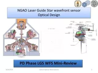
NGAO Laser Guide Star wavefront sensor Optical Design
190 likes | 414 Views
NGAO Laser Guide Star wavefront sensor Optical Design. PD Phase LGS WFS Mini-Review. Introduction. Top left – NGAO LGS beacon geometry on sky showing 4 fixed laser beacons and 3 movable beacons.

NGAO Laser Guide Star wavefront sensor Optical Design
E N D
Presentation Transcript
NGAO Laser Guide Star wavefront sensor Optical Design PD Phase LGS WFS Mini-Review Caltech Optical Observatories
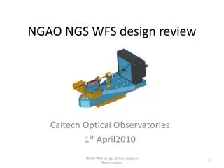
Introduction • Top left – NGAO LGS beacon geometry on sky showing 4 fixed laser beacons and 3 movable beacons. • Top right – NGAO LGSWFS context diagram indication control, data and other interfaces with other NGAO sub-systems. • Bottom right – 3D model of NGAO showing the position of the LGSWFS relative to the other components. Caltech Optical Observatories
Keck NGAO optical relay Left – NGAO LGS beam path starting from the K mirror and ending at the LGS WFS pick off plane. Right – Spot diagram resulting from NGAO relay with the sodium layer distance from telescope aperture being 90 km. One can see RMS spot sizes of 20-45 um for the Fixed asterism and 134-160 um at the Patrolling WFS pick off plane. For reference the scale next to the first field point corresponds to an arcsec. Caltech Optical Observatories
Sub-aperture level aberrations or how I learned to stop worrying about the LGS spots produced by the AO relay Caltech Optical Observatories
To tilt or not to tilt? Based on KAON 685 (NGAO optical relay design) and personal communication with Reni, it was realized that the LGS focal plane delivered by the AO system is tilted. Moreover the tilt varies with change is object (sodium layer) distance. The spots in the previous slide were generated using Version 7 of the NGAO optical design without inducing a tilt at the LGS focal plane. Though the aberrations introduced at the sub-aperture level is small, it may be possible to decrease the input WFE to the LGSWFS. Both the effect of the tilt and the use of an alternate LGS light focusing lens will be explored with Reni. Both the new focusing lens (also a two element window?) and the tilted WFS assembly come at a cost (value TBD). The tilt may need us to either choose a optimal plane to tilt the WFS channels to pick off from or use individual focus stages for the Patrolling WFS’s. Caltech Optical Observatories
Why theta-phi pick-offs? Theta-phi pick-offs as compared to a r-theta pick-off don’t need a translation to compensate for the change in field position and at the same time they don’t need a de-rotation. Though this needs to be prototyped, it is a lot simpler than the HIA r-theta mechanism. More info. : ttp://www.oir.caltech.edu/twiki_oir/pub/Keck/NGAO/WFS/OSM_De-rotation.ppt Caltech Optical Observatories
Why theta-phi pick-offs? Though this pick-off needs to be prototyped, it is a lot simpler than the HIA r-theta mechanism (HIA mechanism also needs to be prototyped). All motion control components are commercial in the theta-phi pick off. Caltech Optical Observatories
Shack Hartmann design maths • Hardy’s ‘p’ parameter choice (based on spot size at the detector) • Stabilization TT Mirror Specification • Evaluation of Differential Focus & Impact of Single LGS WFS Focus Stage • change in radius of curvature (RoC) of the LGS focal plane with change in distance to the sodium layer • Finite size of LGS asterism on-sky • LGS WFS Relay Optical Aberration Specification Caltech Optical Observatories
Shack-Hartmann design parameters – LGS spot size and p parameter Fixed LGSWFS Patrolling LGSWFS Apparent spot size measurement at the detector due to various effects for the fixed tomographic LGS WFS spots (left) and that the apparent spot size at the detector of Patrolling WFS (TT sharpening) LGS WFS spots (right). Charge diffusion term is set to 0 here in order to make an optical estimate of FWHM, which is appropriate for determining the detector pixel scale. [The EBS models charge diffusion and so will the final system when transfer curve calibration is performed on the as-built system.] Caltech Optical Observatories
Stabilization TT Mirror Specification Pupil de-magnification at the TT mirror= 10.949 m /(12.5 mm /1000 mm/m) = 875.92 TT resolution on sky = 1 milliarcsec (say) [The RMS 1D tilt error is 95 milliarcsec] Hence, TT mirror resolution = 0.001 (arcsec) * 875.92 = 0.875 arcsec = 4.2 microradians Capture need, say is, 0.5 arcsec (on sky angle) = 0.5*875.92 “ /206265 (“/rad) = 2.12 millirad Based on the resolution and the capture range we choose the following mirror from Physik Instrumente’s catalog: http://www.physikinstrumente.com/en/products/prspecs.php?sortnr=300700 S-330.8SL has 10 mrad of tilt travel with 0.5 microrad (0.12 milliarcsec resolution on sky) open-loop resolution is the mirror of choice. The mirror has a resonance frequency of 1 kHz with a 1” diameter optic with ¼” thickness. Caltech Optical Observatories
Evaluation of Differential Focus & Impact of Single LGS WFS Focus Stage Cause 1 : change in radius of curvature (RoC) of the LGS focal plane with change in distance to the sodium layer • Cause 2: Finite size of LGS asterism on-sky These effects are deterministic and can be calibrated for. Caltech Optical Observatories
LGS WFS Relay Optical Aberration and Field Stop Specification Spot size (RMS as indicated by Zemax) at the detector = Allocation (arcsec FWHM) / 2.355 (FWHM/RMS) * 21 (um/pixel) / 1.49 (arcsec/pixel) = 0.25 / 2.355 * 21 / 1.49 = ~1.5 um Field stop size = 2.8 arcsec (subaperture size of the fixed LGS asterism size). The field stop will be located after the pick-off, just before the collimator of the sensor. Is this OK? Caltech Optical Observatories
Fixed LGS WFS Pick offs Caltech Optical Observatories
Patrolling LGS WFS Pick offs The pick-off planes are staggered so that all pick-offs can access all field points within the FoR Caltech Optical Observatories
Some comments that will change the design • From the agreed upon drawings of the telescope pupil on the MEMS actuators should use 60 subapertures (not 63). Using these two numbers you get a lenslet pitch of 97.6 um. • Don and I talked at a meeting at UCSC and agreed on 31 and 63 sub-apertures based on a Fried geometry for the 32x32 and 64x64 mirror. This supposed change is not reflected on in the requirements. • From the agreed upon drawings of the telescope pupil on the MEMS actuators should use 30 subapertures (not 31). • Don and I talked at a meeting at UCSC and agreed on 31 and 63 sub-apertures based on a Fried geometry for the 32x32 and 64x64 mirror. Requirements say the same thing as our meeting. And to my best knowledge, the EBS has the 63 and 31 subapertures for the Fixed and Patrolling sensors. Wonder how the Systems Engg. Group didn’t realize the change in architecture when the pupil mapping definition was changed! It certainly didn’t make it into the WFS requirements. • Nutation issue – should we design 60x60 subaperture sensor or even lesser as we can have a already available commercial (PN sensor) detector as a back-up for the 256x256 pixel CCID56? • Need to verify that optics work for 594 nm as well as 589 nm. For instance, the spots at the PNS cameras almost double in size at 594 nm. They’re still only a few microns diameter, but this should be checked. • Valid point - the requirements don’t say that the performance must be the same at 589 and 594 nm; it just says that the sensor needs to operate between 589-594 nm. I’ll re-optimize the PnS sensor design to include both wavelengths. We must also add the requirement on specifying performance specs over the 5 nm range. Caltech Optical Observatories
LGS WFS (the dot-relay less design) 63x63 subaperture Fixed LGS sensor Simplest design with least # of optical surfaces (has been done before). Needs custom alignment jigs and in-house assembly of detector and optics. Must we prototype with a detector we have (ccd39)? Need to handle a bare detector and vacuum and/or hermetically seal it after alignment. 31x31 subaperture Patrolling LGS sensor Caltech Optical Observatories
Fixed LGS WFS design with relay Longer, more optics, but can align easier. Specification on lenslet is looser. Caltech Optical Observatories
Patrolling LGS WFS design with relay Changing the design (due to change in NGAO optical design or change in specification) doesn’t take too much time - probably 2 days to design and two more days to refine update mechanical design and document. But, it would be nice to finalize design ASAP. Uses doublets in the post-lenslet relay. Uses more optics and is longer. Caltech Optical Observatories
Outstanding Items to be completed by PDR: • Stray light (including Rayleigh scatter) analysis • LODM Pupil & lenslet registration scheme • Pupil aberrations at the lenslet. • Simplification of the Optical Design of sensors if possible. • Identifying what all needs to be prototyped in the next phase. • Try to redesign the plano-(parabolic) convex lens to try and provide less aberrated LGS spots at the LGS assembly input. • Cost reduction by finding more economical components. • Draft interface documents between the LGSWFS assembly and the various other sub-systems. • Detailed cost estimate revision, in support of the PD Phase NGAO Cost Book. Caltech Optical Observatories