Download
1 / 30
310 likes | 453 Views
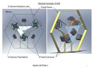
NGAO Laser Guide Star Mechanical. PDR. NGAO Laser Guide Star Mechanical. 1) LGS Asterism Arrangements 2) LGS Fixed Asterisms 2.1) LGS, Lower Fixed Asterism, Design Overview 2.2) LGS Fixed Asterism Probe Arm Design 2.3) LGS Fixed Asterism Gimbal Design

E N D
NGAO Laser Guide Star Mechanical PDR Alex Delacroix
NGAO Laser Guide Star Mechanical 1) LGS Asterism Arrangements 2) LGS Fixed Asterisms 2.1) LGS, Lower Fixed Asterism, Design Overview 2.2) LGS Fixed Asterism Probe Arm Design 2.3) LGS Fixed Asterism Gimbal Design 2.4) LGS Fixed Asterism Camera Assembly Adjustment Design 2.5) LGS, Central Fixed Asterism, Design Overview 3) LGS Patrolling Asterisms 3.1) LGS, Patrolling Asterism, Design Overview 3.2) LGS, Patrolling Asterism, Pick Off Arm Design 3.2.1) LGS, Probe Assembly Optical Design 3.2.1.1) LGS, Probe Assembly Optical Path 3.2.1.2) Static Load on the Lever Motor 3.2.1.3) Static Load on the Crank Motor 3.2.1.4) Probe position accuracy 3.2.1.5) Probe position repeatability Alex Delacroix
NGAO Laser Guide Star Mechanical 3.2.2) LGS, Probe Assembly Mechanical Design 3.2.2.1) LGS, Probe Assembly Limit Switch Mechanical Design 3.2.2.2) LGS, Probe Tip Design 3.2.2.3) LGS, Probe Tip Deflection 3.2.2.4) LGS, Probe Tip Frequency Analysis 3.2.3) LGS, Patrolling Asterism, Lever Assembly Design 3.2.4) LGS, Patrolling Asterism, Crank Assembly Design 3.3) LGS, Patrolling Asterism, Camera Assembly Design 4) LGS, Structure Design Overview 4.1) LGS, Plate Structure Assembly 4.2) LGS, Beam Support Assembly 4.3) LGS, Legs Assembly Alex Delacroix
1) LGS Asterisms arrangement The Lgs is composed of 3 patrolling asterisms and 4 fixed asterisms, equally spaced around the central Field of view. Fixed Asterism, lateral upper Fixed Asterism, center Patrolling Asterism, upper, left Patrolling Asterism, upper, right Fixed Asterism, lateral, lower, right Fixed Asterism, lateral, lower, left Patrolling Asterism, lower Current Mass Estimate: 80 Kg LGS arrangement Alex Delacroix
2) LGS Fixed Asterism The Lgs fixed asterism is composed of three lateral probes pointing toward the center of the science field within a diameter of 14.5mm (20”) (FR-2360) and one central Channel. Each Channels are installed thru a three point kinematic mount, shimmed as required. Fixed Asterism, lateral, upper Kinematic mount Fixed Asterism, center Fixed Asterism Field of View Fixed Asterism, lateral, lower, left Current Mass Estimate: 55 Kg Fixed Asterism, lateral, lower, right Fixed Asterism arrangement Alex Delacroix
2.1) LGS, Lower Fixed Asterism, Design Overview The fixed asterisms is adjustable in pitch and yaw about its focus point. The camera assembly is mounted on a gimbal, holding the fold mirror , is bolted on the probe body that also receives the collimator lens Probe (Fold mirror holder) Probe Body (Collimator lens holder) Probe Bracket Collimator Lens holder Focus Lens holder Adjustable 0.25mm per rev. Thorlabs ST1XY-A Lenslet holder Tip Tilt PI S330-2 Field stop (FR-2397) Relay Lens holder Tip Tilt Bracket CCD Adjustment Knob Newport AJS100-0.5 Mounting base Post 1in dia Thorlabs RS2 2837-EOW Mounting Bolts Gimbal Assembly Lateral Fixed Asterism design Alex Delacroix
2.2) LGS Fixed Asterism Probe Arm Design The Fold mirror is bonded at the extremity of a tubular probe design, bolted to the body, sandwitching the Collimator lens thru a soft o-ring, compressed to hold the lens in place against a machined receptacle. Probe Bracket Probe Body Soft O-ring (Shore A: 50, Buna-N ) Probe Mirror (bonded) Collimator lens Probe Arm Assembly (Cross Section) Alex Delacroix
2.3) LGS Fixed Asterism Gimbal Design The Camera assembly is mounted on an aluminiumgimbal thru shoulder screws and bronze bushings. The necessary gap and relative position of the gimbal is controlled using shoulder shim stocks. Shim Stock , Stainless Steel ID .501 x .005” +/-.0005” Thk Mc Master 94773A616 Camera Assembly Probe Body Sleeve Bearing, flanged, bronze Ø 5/8” OD x Ø 1/2” ID x ½” Lg Mc Master 7815K29 Shoulder Screw , Stainless Steel Ø1/2” x ¾” Lg Mc Master 94035a503 Shoulder Screw , Stainless Steel Ø3/4” x 1-1/4” Lg Mc Master 90298a837 Gimbal Shim Stock, Stainless Steel ID .751” x .020” +/-.0025” Mc Master 94773A720 Sleeve Bearing, flanged, bronze Ø 1” OD x Ø 3/4” ID x 1” Lg Mc Master 7815K49 Gimbal Assembly (Cross Section) Mounting Base Alex Delacroix
2.4) LGS Fixed Asterism Camera Assembly Adjustment Design The Camera Assembly pitch and yaw adjustments are located 250mm away from the axis. The 1 inch travel adjustment knobs with a 0.7µm resolution gives the system a 0.57” angular resolution. (tan α = 0.7 E-6 / 250 E-3 = 28 E-7 , α= 160E-6 deg = 0.57 “) Camera Assembly Adjustment Knob Newport AJS100-0.5 Steel plate Rod, threaded TBD Compression Spring TBD Camera Assembly Adjustment (Cross Section) Mounting Base Alex Delacroix
2.5) LGS, Central Fixed Asterism, Design Overview The Central fixed asterism differs in design only by the absence of a probe, rendered unnecessary by it’s central location in the sensor. Camera Assy Fold Mirror Gimbal Assembly Central Fixed Asterism Mounting base Alex Delacroix
3) LGS, Patrolling Asterism, Design Overview Patrolling asterisms are located 120 degrees apart from each other and are pointing the probes toward the 120” FoV Patrolling Asterism, upper, left Patrolling Asterism, upper, right 120” FoV (FR-2362) Patrolling Asterism, lower Current Mass Estimate: 25 Kg Patrolling Asterism Alex Delacroix
3.1) LGS, Patrolling Asterism, Design Overview The Patrolling Asterism is composed of two distinct sub assemblies: The Pick off arm Assembly and the Camera Assembly. Camera Assembly Pick off Arm Assembly Current Mass Estimate: 8 Kg Patrolling Asterism Alex Delacroix
3.2) LGS, Patrolling Asterism, Pick Off Arm Design • The Pick off arm Assembly is composed of three distinct sub assemblies: • The Probe Assembly • The Lever Assembly • The Crank Assembly • The Course limiter pattern is a single part installed at the LGS Assembly level. Probe Assembly Course limiter pattern Lever Assembly Crank Assembly Pick off Assembly Alex Delacroix
3.2.1) LGS, Probe Assembly Optical Design The Pick off arm Assembly is designed to answer the optical equation: a = b & c = d with a + b = x (c + d) and a = a1 + a2 Lever Arm length = b + a2 Solving for a2 2a2 = Lever Arm length - a1 a2 = (Lever Arm length - a1 )/2, so, with a = b = 120 Collimator Lens (L1) Probe (FM1) L2 TT AO Focus PO Focus a1 a2 b c d a Lever Arm Table 1 Alex Delacroix
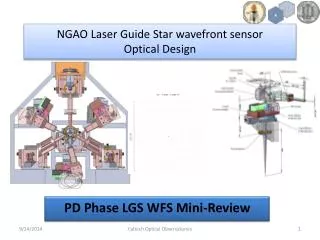
3.2.1.1) LGS, Probe Assembly Optical Path The Patrolling Asterism is composed of two distinct sub assemblies: The Pick off arm Assembly and the Camera Assembly. Fold Mirror Tip Tilt Collimator Lens Periscope Focus Lens Patrolling Asterism (Cross Section) Alex Delacroix
3.2.1.2) Static Load on the Lever Motor Total Mass: 1,240 grams ( 12.2N ) CG located at the Axis of rotation, 38 mm above the Lever motor Interface. Torque at the Lever Rotation Stage Interface: 0.038 X 12.2 = 0.46 Nm Well below the manufacturer recommendation of 3 Nm This gives a Factor of Safety of 3 / 0.46 = 6.5 Limit Switch Assembly 50 grams Tip Tilt OIM100 340 grams ½ in dia Collimator Lens 1 gram Probe 30 grams CG Location Lever Arm 454 grams Counterweight 300 grams Fig. 11 Alex Delacroix
3.2.1.3) Static Load on the Crank Motor Total Mass: 3,525 grams (35N) CG located at the Crank Axis of rotation, 60 mm above the Lever motor Interface. Torque at the Crank Rotation Stage Interface: 0.060 X 35 = 2.1 Nm Well below the manufacturer recommendation of 6 Nm This gives a Factor of Safety of 6 / 2.1 = 2.8 Lever Arm Assembly 1,240 grams CG Location Lever Motor PI M-037.DG 650 grams Lever Adaptor 455 grams Crank Adaptor 435 grams Counterweight 700 grams Periscope Assy 60 grams Alex Delacroix
3.2.1.4) Probe Position Accuracy • Position Accuracy at the longest probe: OSM #3, a1 = -20 • Lever Arm Length: 260mm • Crank arm Length: 41.8mm • Lever Stage M-037.DG Design resolution: 0.000034° • Crank Stage M-038.DG1 Design resolution : 0.000035° • Lever arm position accuracy: 250mm X tan 0.000034° = 0.00015mm • Crank arm position accuracy: 290mm X tan 0.000035° = 0.00018mm • __________ • = 0.00033mm • = 0.00045” Resulting position accuracy at the tip of the probe = 0.00033mm = 0.45 mas 3.2.1.5) Probe Position Repeatability • Position Repeatability at the longest probe: OSM #3, a1 = -20 • Lever Arm Length: 260mm • Crank arm Length: 41.8mm • Lever Stage M-037.DG Design repeatability: 30 μrad = 0.0017° • Crank Stage M-038.DG1 Design repeatability: 20 μrad = 0.0011° • Lever arm position repeatability: 250mm X tan 0.0017° = 0.007mm • Crank arm position accuracy: 290mm X tan 0.0011° = 0.005mm • __________ • Resulting Repeatability = 0.012mm = .016” = 16 mas Fig. 13 Alex Delacroix
3.2.2) LGS, Probe Assembly Mechanical Design The Collimator lens, installed inside the Probe body, is held in place by a Soft o-ring installed inside the collimator lens spacer, that is held by the Probe. The Fold mirror is bonded at the tip of the probe. The Probe Assembly needs to be balanced about its axis of rotation to avoit placing uncontrolled loadings on the Lever Rotation Stage. 1 inch dia Tip Tilt Optics In Motion 100 Limit Switch Assembly Probe Body Soft O-ring (Shore A: 50, Buna-N ) Fold Mirror Collimator Lens Collimator Lens spacer Probe Probe Arm Assembly (Cross Section) Alex Delacroix
3.2.2.1) LGS, Probe Assembly Limit Switch Mechanical Design This device is a wobbler limit switch that gives direction indication. The wobbler is composed of a Ball Bearing Track Roller (Mc Master 3668K2), a steel shaft mounted on three compression springs, resting on 3 load cells. The load cells give direction and distance measurements. Operation: Shortly after the arm deviates from its allowed path, the roller will contact the custom track, forcing the spring mounted wobbler base to exercise a pressure on a one or two of the load cells, signaling a trajectory error. Retraction can then be safely done by rotating the crank motor in any direction and rotating the Lever arm in accordance with load cells signals. Ball Bearing Track Roller Mc Master 3668K2 Threaded Steel Shaft Spring Mounted base Load cells Honeywell BL912A Load cell Honeywell BL912A Compression Spring WobblerAssembly Alex Delacroix
3.2.2.2) LGS, Probe Tip Design The Field of View at the Focal Plane is Ø 5” (3.635mm) The Field of View at the probe is defined by it’s distance from the Focal Plane / f# The probe Fold Mirror intercept the light beam at a 45 degree angle creating an elliptical projection at a distance a1 from the Focal plane. (See Fig. 4) The minimum diameter of the mirror needs to be larger than the Ellipse Major Diameter. The Larger Fold mirror will be at the furthest distance from the Focal plane OSM #1 (a1 = -20) The Patrolling Asterism LGS WFS channels shall be able to measure wavefronts from two LGS beacons separated by 10 arcseconds. FR-3430 Light from Focus Ellipse Minor Diameter: d = d at Focus Plan + (a1 / f#) = 5 X 0.727 + (20 / 13.66) = 3.635 + 1.464 d = 5.10 mm Ellipse Major Diameter: D = d√2= 5.1√2 D = 7.21 mm Light to L1 FM1 Ellipse Minor Diameter: d = d at Focus Plan + (a1 / f#) = 5 X 0.727 + (5 / 13.66) = 3.635 + .366 d = 4.00 mm Ellipse Major Diameter: D = d√2= 4√2 D = 5.66 mm Probe Tip Ellipse Minor Diameter: d = d at Focus Plan + (a1 / f#) = 5 X 0.727 + (10 / 13.66) = 3.635 + .732 d = 4.37 mm Ellipse Major Diameter: D = d√2= 4.37√2 D = 6.18 mm Probe is sized to 8mm Diameter for commonality Alex Delacroix
3.2.2.3) LGS, Probe Tip Deflection • Deflection analyzed on the longest Inclined probe (OSM #2) Probe Deflection • Mass of the probe w = mg = 0.01 Kg x 9.81 ms-2 = 0.098N • Moment of Inertia: I = bh3/12 = 4.57 x 7.643/12 = 169.8 mm4 • 6061-T6 Module of Elasticity: E = 68,800 N/mm2 • Max Deflection: ν = wL3 / 8EI • ν =0.098 X 1003 / (8 X 68,800 X 169.8) • ν = 98000/ 93457920 • ν = 0.001mm Probe Length Max Probe Deflection, at rest, under it’s own weight: 1µm Alex Delacroix
3.2.2.4) LGS, Probe Tip Frequency Analysis Lowest Frequency OSM #3 OSM #2 OSM #1
3.2.3) LGS, Patrolling Asterism, Lever Assembly Design The Lever Assembly needs to be balanced about its axis of rotation to avoid uncontrolled loadings on the Crank motor. However, to compensate for undesired backlash of the Lever rotation stage, a slight, almost constant load is applied to the Probe Arm by the Backlash compensating spring system. Backlash compensating spring Lever Adaptor Rotation Stage PI M-037.DG Crank Adaptor Periscope Cable Boom Cable Wrap Energy Chain Z045 Rotation Axis Lever Assembly (Cross Section) Lever Assembly Alex Delacroix
3.2.4) LGS, Patrolling Asterism, Crank Assembly Design The Crank Assembly holds the Crank Rotation Stage, the focus Lens and the Crank Backlash compensating spring system. Rotation Stage PI M-038.DG Folded Focus Lens holder Crank Bracket Backlash compensating spring Crank Assembly Alex Delacroix
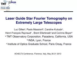
3.3) LGS, Patrolling Asterism, Camera Assembly Design The Patrolling Asterism Camera Assembly is made of a ¾ in thick Aluminum Honeycomb panel potted with aluminum inserts. It receives the Sensor optical mounts and the Pick off arm assembly. The panel is installed on the LGS Structure through shim stocks for tip tilt adjustment. Relay Lens holder Lenslet holder CCD Tip Tilt PI S330-2 Collimator Lens holder Fold Mirror Aluminum HoneyComb Panel ¾ in thick Three point mount 5/16 Bolts and Shim stock Patrolling Asterism, Camera Assembly Alex Delacroix
4) LGS, Structure Design Overview • The Structure is composed of: • The Plate Structure assembly • The Beam Support Assembly • The Legs Assembly X Plate Structure Assembly Y Beam Support Assembly Pole Assembly Structure Design Alex Delacroix
4.1) LGS, Plate Structure Assembly The Structure, made of 1 inch and ¾ inch Thick bolted Aluminum plates, is rigidly holding each Asterisms. Each channel can be moved individually and locked in place thru a three point mount scheme. Three Hoist Rings are provided for lifting the Assembly with a Crane. Hoist rings 5/16 Bolts x 1.5in Lg 860 mm ¼ in Dia Shear pin (Match drilled in place after assembly and inspection) 875 mm 616 mm Current Mass Estimate: 90Kg Plate Structure Assembly Alex Delacroix
4.2) LGS, Beam Support Assembly One side of the Beam Support Assembly carries the LGS Translation mechanism, composed of two Deltron Slide bearings and a motorized stage (FR-2378 ). The other side of the Beam Support Assembly carries the LGS Kinematic Mount Scheme Composed of three receptacles: A Cone, a groove and a Flat. Three Hoist rings are also provided to tie-down the Structure to the telescope Nasmyth. The Beam Support Assembly is made of standard Aluminum IPN and plates Welded. The alignment of the structure relative to the Bench can be done by shimming between this assembly and the Structure assembly. The LGS WFS support structure shall be aligned to the required optical bench interface point to better than 1 mm. FR-2375 The LGS WFS support structure shall be aligned to the required optical bench interface optical axis direction to better than 2 arcminutes (physical angle at the interface point) FR-2376 Tie down Hoist rings Translation Stage Newport MTM250CC 0.1 µm resolution Groove Cone Flat High Precision Series Crossed Roller Slides 10 inches Travel, accuracy .00004 in/in Deltron HPRS 5-10 Current Mass Estimate: 65 Kg Beam Support Assembly Alex Delacroix
4.3) LGS, Legs Assembly The Legs are the link between the Telescope Nasmyth platform and the LGS structure. They are made of three different materials to compensate for dome temperature variations in conformity with the stability requirement. The LGS WFS support structure shall be stable to a level better than (x,y,z,thetax,thethay,thethaz) = (TBD, TBD, TBD, TBD, TBD, TBD) with respect to the telescope coordinate system. FR-2377 Leg Inner shell Aluminium CTE 25 µm/m/°C LGS Leg Core Titanium CTE 8 µm/m/°C 860 mm Leg Outer shell Stainless Steel CTE 14 µm/m/°C Legs Leg Assembly (Cross Section) Legs Assembly Current Mass Estimate: 65 Kg Alex Delacroix