Download
1 / 25
260 likes | 638 Views
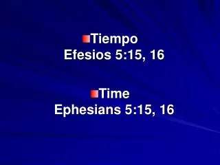
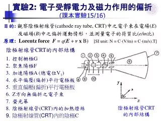
實驗 2: 電子受靜電力及磁力作用的偏折 ( 課本實驗 15/16). 目的 : 觀察陰極射線管 (cathode ray tube, CRT) 中之電子束在電場 ( E ) 及磁場 ( B ) 中之偏折運動情形,並測量電子的荷質比 ( e/m 比 ) 原理 : Lorentz force F = q ( E + v x B) [SI unit: N = C · (V/m) = C·(m/s).T]. 陰極射線管 CRT 的內部結構 控制柵極 G 聚焦陽極 F 加速陽極 A ( 總電位 V 1 ) 水平偏壓 ( 偏折 ) 平行電極板

E N D
實驗2: 電子受靜電力及磁力作用的偏折 (課本實驗15/16) 目的:觀察陰極射線管(cathode ray tube, CRT)中之電子束在電場(E)及磁場(B)中之偏折運動情形,並測量電子的荷質比(e/m比) 原理: Lorentz force F = q(E + v x B) [SI unit: N = C·(V/m) = C·(m/s).T] • 陰極射線管CRT的內部結構 • 控制柵極G • 聚焦陽極F • 加速陽極A (總電位V1) • 水平偏壓(偏折)平行電極板 • 垂直偏壓(偏折)平行電極板 • Z方向無偏折之電子束 • 螢光幕 • 陰極射線管(CRT)內的加熱燈絲 • 陰極射線管(CRT)內的陰極C 陰極射線管CRT的內部結構
陰極射線管的工作原理Operation Principle of CRT • I. 在水平和垂直偏折平行電極板(4,5)無外加偏壓信號時: • 陰極射線管內的加熱燈絲(8)將陰極C(9)加熱放出熱電子 • 經控制柵極G(1), 聚焦陽極F(2)及加速陽極A(3)(總電位V1)後 • 電子往Z方向(6)做等速運動,mvz2/2 = eV1 vz = (2eV1/m)1/2 • 電子打到螢光幕(XY面)(7)上的中心位置,形成一亮點。 電子質量 m = 9.11 x 10⁻³¹ kg 電荷 q = -e = -1.60 x 10⁻¹⁹ C As V4 = 0 V5 = 0 陰極射線管CRT的內部結構
Cathode Ray Tube(CRT) • The electrons are deflected in various directions by two sets of plates. • The placing of charge on the plates creates the electric field between the plates and allows the beam to be steered. • Commonly used to obtain a visual display of electronic information in oscilloscopes, radar systems, televisions, etc.. • Be a vacuum tube in which a beam of electrons is accelerated and deflected under the influence of electric or magnetic fields.
Cathode Ray Tube (CRT)- is one of the main elements of an oscilloscope. • A CRT is commonly used to obtain a visual display of electronic information in oscilloscopes, radar systems, televisions, etc. • The CRT is a vacuum tube in which a beam of electrons is accelerated and deflected under the influence of electric or magnetic fields. • The tubes are produced with electrostatic and electromagnetic control, where electrostatic or magnetic fields deviate the electron beam respectively. • The principle scheme of CRT has electrostatic control as well as the motion of the electrons in the beam drawing a sinusoid on the screen of oscilloscope.
Configuration of CRT • CRT consists of 6 sections: • Glass bulb evacuated to a high vacuum (真空管) • Cathode (a source of electrons,電子槍陰極) • Cathode heater (陰極加熱器) • Electrodes for brightness and focus control, several accelerating anodes (亮度、聚焦、加速控制柵極) • Pairs of horizontal and vertical capacitor plates deviating the electron beam • Fluorescing screen (螢光幕)
Discharge Tube • It was observed that whenever the glass tube filled with air at low pressure and • sealed with electrodes at both the ends was subjected to about 10,000 volts of electricity, • a strange glow was produced around the edges of the wide end of the glass tube, irrespective of the type of gases present in it. • The glass tube with sealed electrodes is called discharge tube. Discharge Tube Electron Gun
Cutaway rendering of a color CRT • Electron guns • Electron beams • Focusing coils • Deflection coils • Anode connection • Mask for separating beams for red, green, and blue part of displayed image • Phosphor layer with red, green, and blue zones • Close-up of the phosphor-coated inner side of the screen
CATHODE-RAY TUBE (CRT)- is one of the main elements of an oscilloscope. • One of anodes, which accelerate the electrons, is placed close to the screen. • The high positive voltage is applied to this electrode. • Under the action of the applied voltage the electrons are moved with acceleration from cathode to anode. • In the absence of the voltage applied to deviating plates of the capacitor the electron beam will be incident on the screen in the center brightening a point in the fluorescing layer. • In oscilloscope the analyzed signal after amplification is applied to vertical deviating plates, while the periodic sawtooth signal is applied to horizontal plates.
http://physics-animations.com/Physics/English/osc_tmp.htm • As a result the electron beam "draws" the dependence of the investigated signal on time on the screen of the tube. • Reaching the right side of the screen the beam has to be returned to an initial point at the left side. • Thus, if CRT is not blanked during this retrace, then the beam will leave a track crossing the image of investigated signal. • For this reason, during retrace a negative voltage is applied to control electrode situated near to cathode and electrons are locked by such a way at the electron gun. • As a result, the electron beam will be discontinuous, as shown in animation.
Related Web Sites for CRT Animation • http://highered.mcgraw-hill.com/sites/0072512644/student_view0/chapter2/animations_center.html • http://physics-animations.com/Physics/English/osc_tmp.htm • http://www.sciencemuseum.org.uk/on-line/electron/section2/shockwave2.asp • The Cathode Ray Tube site: http://members.chello.nl/~h.dijkstra19/page3.html • How Television Works: http://www.howstuffworks.com/tv.htm/printable
2. 電子在直流電場中之偏折: 利用水平電板X(4)及垂直電板Y(5)所提供的電壓,產生均勻電場(E),使電子束偏折,如電板Y長L, 兩板距離d, 直流電位差V2 (E = V2/d),電子離開電板後距螢光幕D,則電子在Y方向偏折SE,使螢光幕(XY面)在Y軸 SE 處產生一亮點。 X:等速直線運動 Y:等加度運動 X, Y等速直線運動
3. 電子在交流電場中之偏折: 若在電板Y加交流電頻率 f = /2 = 1/T 因高頻,電子在螢光幕成一長為l的亮線 Note:一般家電 Vrms = 110 V, f = 60 Hz
4. 電子在磁場中之偏折 利用共軸雙線圈螺線管之均勻磁場(B)來偏折電子束 如磁場在x方向 (長L),電子離開磁場後距螢光幕 D 則電子在Y方向偏折 SB ( Sm) 螢光幕(XY面)Y軸上SB有一亮點 5. 同時在電場及磁場的作用下 並使電子不偏折 SE + SB = 0 eE = evzB vz = E/B 代入 SE 或 SB 即可求電子的荷值 (e/m) 比
實驗步驟: I. 陰極射線管電源 1. 陰極射線管(X = 60 mm, Y =54 mm, D = 115 mm, L = 11 mm, d = 1.65 mm) 插入CRT基座(Unilab 031.502) X為X電板輸入端 Y為Y電板輸入端 A1為最後加速陽極 Z接柵極 2. CRT基座接CTR電源供應(032.332) 之五腳CRT插座(tube supply) 注意:高壓電源! 接電路前, 確定電源供應器 開關為關(off)(燈暗) 3. 調整CRT亮點之 亮度(brill)(加速陽極) 及焦距(focus)(聚焦陽極)
II、電場偏折 1. 放大器(amplifier)(2)(032.842)接CRT電源供應器(1) (032.332)之aux unit直流電源(6 V) 2. 產生交流電場: 電源供應器(1)之交流電壓(6 Vrms)接到放大器之 交流耦合A (alternating coupling)輸入端 +共用端C (common) AC: 只有ac信號進入(串聯電容器) DC: 直流耦合D (direct coupling): ac/dc信號均可進入 3. 放大器之X/Y輸出端接CRT基座(3) (031.502)之垂直Y電板輸入 4. 利用放大器之增益(gain)及 移動 (shift) 鈕,觀察及調整Y方向 之亮線位置及長度/電壓振幅值 l = 2Vm (校正後) Y靈敏度(sensitivity): 23 V/1 cm (Q):如何量週期T? (1) (3) (2)
III.交流電壓波形及頻率 1. 時基產生器(2)產生掃描鋸齒波 (掃描週期可調) 2. 時基產生器(2)同步掃描鋸齒波 (掃描週期可調)輸出接水平 放大器(3)輸入DC端(下頁) 3. 水平放大器(3)之輸出端接 CRT基座之水平電板輸入(5) (水平輸入為時間t)(校正後)
(1) 3. (5)垂直Y電板輸入不變 但垂直放大器(4)輸入接DC端 (垂直輸入為電壓V) 4. 放大器輸入A端同步接 時基產生器(2)(032.892) (time base generator) 同步輸入端(sync) 5. 觀查CRT之波形Y(X) = V(t), 量振幅(Vm)及週期(T) (2) (3) (4) (5)
IV. 磁場偏折 • 產生磁場:直流電源供應器(5) 接到共軸雙線圈螺線管(2) (031.402),線圈數為N = 3000圈 + 3000圈。 • 利用可變電阻(4)及安培計(3) 調整及測量電流(I)大小,因磁場B NI,所以可求算B值。 • 3.共軸雙線圈螺線管放於CRT 基座(1)之CRT上。 • 4.利用不同方式測量電子的e/m比值。 (1) (2) (5) (3) (4)
實驗3: 示波器操作 (課本實驗17) 目的: 瞭解示波器(oscilloscope)之基本原理及操作 原理: 見[電子受靜電力及磁力作用的偏折]實驗 (例): 示波器 TRIO CS-1022 (附錄B) 1. 陰極射線管(CRT)控制 (Z軸控制) (見下頁圖) 電源及指示燈(power) (13,14)(保護儀器,注意安全) 接地(ground, GND) (15)去除靜電,避免火花放電(保護儀器,注意安全) 校正(probe adjust) (16) 方波, f = 1 kHz, Vp-p = 2Vm = 0.5 V 軌跡旋轉(trace rotation) (17)去除附近磁場/地磁影響 聚焦(focus) (18)聚焦陽極 強度(intensity) (19) 加速陽極 (3-1)
示波器正面: (例) TRIO CS-1022 Y -- X lZ l T (3-2)
2. 垂直(vertical)(Y軸)及水平(horrizontal)(X軸)控制 (以Y為例) 軌跡位置(position) (1)垂直位置 (拉出時放大十倍) 可變/校正控制(variable/cal) (2) 轉到校正(cal)位置, 靈敏度範圍: 1 mV/格 – 5 V/格 靈敏度(sensitivity/volts) (3)信號放大及衰減 輸入模式(ac-GND-dc) (4) ac: alternating coupling (交流) GND: no signal (校正基線) dc: direct coupling (交流+直流) 輸入(input) (5) BNC型插座 控制模式 (mode) (12) ch 1: Y signal only ch 2: X signal only add: X+Y alt, chop (其它用途) (3-3)
3. 時基(T)掃描 (X無輸入) 觸發水平/斜率(trig level/slope) (22): 穩定波形 (+/0) 觸發耦合(trig coupling) (23): ac 觸發源(trig source) (24) ch 1: Y 內源 (觸發鋸齒波掃描) ch 2: X line (電源觸發) ext (外源觸發) (接21) 觸發模式(trig mode) (25) auto (自動觸發) norm (正常) X – Y 可變/校正控制(variable/cal) (26) 轉到校正(cal)位置, 靈敏度範圍: 0.2 ms/格 – 0.5 s/格 掃描時間(sweep time) (27)信號放大及衰減 軌跡位置(position) (28)水平位置 (拉出時放大十倍) (3-4)
示波器方塊圖(block diagram): (例) National VP-5107T Y X/ T calibrator power/Z (3-5)
交流信號產生器(signal generator) (例) TRIO AG-203 電源(power) (1,2)(保護儀器) 輸出衰減(attenuation): 0 - -50 dB 6個衰減級距 (3) I(dB) = 10.log10(I/I0) 0 dB =1, -10 dB = 10-1 -20 dB = 10-2, -30 dB = 10-3 -40 dB = 10-4, -50 dB = 10-5 信號輸出(output) (4) 波型(wave form): 正弦波,方波 (5) 頻率(frequency): 10 Hz – 1 MHz 5個頻率級距(range) (6,8,9,10) x1 (10-100 Hz), x10, x100 x1k, x10k (100 kHz – 1 MHz) 振幅(amplitude): 連續調整(7) (3-6)
實驗: 1. 基本操作熟悉 2. 檢查放大器靈敏度及校正 3. 檢查時基靈敏度及校正 4. X-Y操作 X,Y輸入正弦信號 觀察右圖合成波形 Vx + Vy 5. 頻率(f)測量 Y輸入正弦信號: Vy(t) = Vmsin(2pf.t) (3-7)