Download
1 / 24
240 likes | 400 Views
BNL ERL Cryomodule. Andrew Burrill ERL 2007. What is it, and why are we building it?. ERL prototype is a test bed for the RHIC II upgrade High current design 0.5A 1.4 nC/bunch as well as 5 nC/bunch 54 MeV RHIC II State of the art accelerating cavity, injector and novel injection scheme

E N D
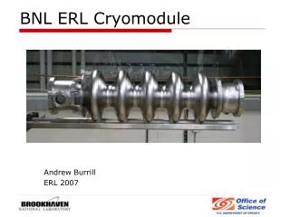
BNL ERL Cryomodule Andrew Burrill ERL 2007
What is it, and why are we building it? • ERL prototype is a test bed for the RHIC II upgrade • High current design 0.5A • 1.4 nC/bunch as well as 5 nC/bunch 54 MeV RHIC II • State of the art accelerating cavity, injector and novel injection scheme • Real high current photocathode choices • Custom laser system What the cryomodule needs to deliver • High current acceleration while avoiding beam breakup • Ensure all HOM’s are carried to the load • Provide good accelerating gradient • Reduce sensitivity to acoustics A. Burrill ERL Workshop, 2007
ERL Layout A. Burrill ERL Workshop, 2007
Courtesy Doug Holmes A. Burrill ERL Workshop, 2007
Cavity String assembly Courtesy Doug Holmes A. Burrill ERL Workshop, 2007
Cryomodule interface Courtesy Doug Holmes A. Burrill ERL Workshop, 2007
Schedule • Weld He vessel and assemble string Q3 07 • Assemble to space frame and ship to BNL Q3 07 • Install all remaining instrumentation, shielding, vacuum vessel install in 912 Q3 07 • Begin cold emission testing Q4 07 A. Burrill ERL Workshop, 2007
Cavity Parameters Courtesy Ram Calaga A. Burrill ERL Workshop, 2007
Design benefits • No trapped HOM’s • Very high BBU threshold, > 1.8A • 24 cm water cooled Ferrite absorbers capable of 12 kW HOM power A. Burrill ERL Workshop, 2007
Cavity Mechanical Stiffness A. Burrill ERL Workshop, 2007
Cavity stiffness A. Burrill ERL Workshop, 2007
Tuner Courtesy Jim Rank A. Burrill ERL Workshop, 2007
Fundamental power coupler A. Burrill ERL Workshop, 2007
Activity Summary • Cavity designed by BNL and fabricated by AES • Cavity baseline measurements were made at AES, then cavity was shipped to JLAB for processing • Physical dimensions of the cavity made processing a challenge and several new things were learned • Initial cavity performance was less than expected so several R&D efforts were undertaken to reach our target gradient • Cavity is now ready to have He vessel welded on and one more VTA pass made prior to assembly into the cavity string for shipment back to BNL A. Burrill ERL Workshop, 2007
Processing summary • Initial cavity performance was less than expected • End-flanges were modified to eliminate heating, this greatly improved performance • He processing was subsequently used to help improve performance • Final improvements came from a low temperature 110°C vacuum bake A. Burrill ERL Workshop, 2007
Initial Cavity Performance A. Burrill ERL Workshop, 2007
Effects of Helium Processing A. Burrill ERL Workshop, 2007
Benefits of a low temperature bakeout at 110 degrees A. Burrill ERL Workshop, 2007
Indium contamination • Compromising an indium seal while baking a cavity is not the end of the world, and performance can be easily recovered • Cavity was cleaned by flowing conc. Nitric acid for one hour • Nitric dissolves indium but does nothing to Nb, unlike BCP which etches Nb at a much faster rate than indium A. Burrill ERL Workshop, 2007
High pressure rinsing does not have to be done in a cleanroom, it probably should be but…. • Our HPR system was configured in the chemistry room with a N2 gas purge. • Cavity exhibited no field emission after several passes through the HPR system A. Burrill ERL Workshop, 2007
Low temperature bake-out offered significant improvement • Cavity was placed in a bake-out box and mounted with 7 thermocouples to ensure uniform heating A. Burrill ERL Workshop, 2007
Other techniques that could be attempted • High Temperature post-purification bake at 1300 C in presence of Ti to improve RRR as well as anneal and recrystalize cavity, increase crystal size and help eliminate high field Q slope. • Electro-polish, remove surface roughness, increase gradient by reducing local heating A. Burrill ERL Workshop, 2007
Conclusion • The cavity has reached a very high level of performance, 20.5 MV/m, with low field Qo of 4.5e10 • Assembly into a cryomodule is progressing nicely • Cold emission testing should begin fall of 2007 with a complete ERL in early 2009 A. Burrill ERL Workshop, 2007
Acknowledgements Ilan Ben-zvi, R. Calaga, H. Hahn, V. Litvinenko G. McIntyre, H. Hseuh, C. Pai, D. Phillips, K. Smith, A. Zaltsman AES D. Holmes, M. Cole, A. Favale, J. Rathke, T. Schultheiss JLAB P. Kneisel, R. Rimmer, L. Phillips, J. Prebel, J. Mammoser, J. Saunders ORNL R. Campisi, K Yong Many many others I forgot to mention Supported by DOE/NP, BNL directors office, JTO, ONR A. Burrill ERL Workshop, 2007