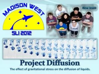
The Impact of Gravitational Stress on Liquid Diffusion: SLI 2012 Project Summary
This report details the SLI 2012 project focusing on the effect of gravitational stress on liquid diffusion, specifically through a rocket flight experiment. It includes an analysis of the major milestones achieved, with a GANTT chart and detailed mission profile. Key events such as ignition, apogee, and parachute deployment are documented along with crucial data on vehicle specifications and materials. The project aims to discern the influence of acceleration and vibrations on dye diffusion, using advanced digital imaging techniques for analysis. Results from scale model tests and lessons learned are included to ensure future success.

The Impact of Gravitational Stress on Liquid Diffusion: SLI 2012 Project Summary
E N D
Presentation Transcript
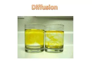
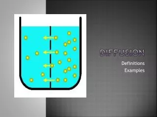
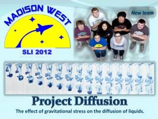
New team SLI 2012 ProjectDiffusion The effect of gravitational stress on the diffusion of liquids.
Mission Profile Chart Event 3: Apogee at 17s, 5252ft Coast Drogue descent Apogee prediction updated based on data from scale model flight (Cd=0.48): 5252ft Event 2: Burnout at 2.24s, 1000ft Event 4: Main parachute deployment at 84s, 700ft Event 5: Landing at 110s, 0ft Event 1: Ignition at 0s, 0ft
Vehicle Success Criteria • Motor ignition • Stable flight • Altitude of 5,280 feet AGL reached but not exceeded(most current prediction: 5252ft) • Both drogue and main parachute deployed • Vehicle returns to the ground safely with minimal damage • Safe recovery of the booster
Vehicle Drawings CP 83.1” from nosecone CG 65.6” from nosecone Static margin 3.2 calibers Length 108” Diameter 5.5”(body tube), 4”(booster) Liftoff Weight 21.5 lb Motor Aerotech K1050W
Construction Materials • Body:5.5”/4.0” LOC Precision fiber tubing • Fins: 1/32” G-10 fiberglass + 1/8” balsa sandwich • Couplers: LOC Precision with stiffeners • Bulkheads, centering rings: 1/2” plywood • Motor mounts: 54mm Kraft phenolic tubing • Nosecone: Plastic nose cone • Rail buttons: standard nylon rail buttons • Motor retention system: Aeropack screw-on motor retainer • Anchors: 1/4" stainless steel U-Bolts • Epoxy: Locktite epoxy
Motor Selection • We selected the AT-K1050W 54mm motor to propel our rocket to but not exceeding an altitude of 5280ft AGL • The AT-K1050W motor provides an appropriate thrust to weight ratio for our vehicle (9.8). Mach delay of 4 seconds will be set on both deployment altimeters
Altitude Profile Apogee at: 5252ft, 17s
Acceleration Profile Max acceleration: 16 Gees
Velocity Profile Maximum velocity: 520 mph Mach number: 0.72
Ejection Charge Calculations Wp=dP*V/(R*T) • Wp - ejection charge weight [g] • dP - ejection pressure (15 [psi]) • V - free volume [in3] • R - universal gas constant (22.16 [ft-lb oR-1 lb-mol-1]) • T - combustion gas temperature (3,307 [oR])
Calculated Ejection Charges Charges will be finalized via static ejection tests. Tests carried out with the scale model indicated that average increase of 30% against calculated values may be needed for GOEX 4F powder.
Verification Plan • Tested Components • C1: Body (including construction techniques) • C2: Altimeter • C3: Accelerometer • C4: Parachutes • C5: Fins • C6: Payload • C7: Ejection Charges • C8: Launch System • C9: Motor Mount • C10: Beacons • C11: Shock Cords and Anchors • C12: Rocket Stability
Verification Plan • Verification Tests • V1 Integrity Test: force applied; verifies durability. • V2 Parachute Drop Test: tests parachute functionality. • V3 Tension Test: force applied to shock cords; tests durability. • V4 Prototype Flight: tests feasibility of vehicle with scale model. • V5 Functionality Test: tests basic functionality of device on ground. • V6 Altimeter Ground Test: simulate altitude changes; verifies preset altitude events fire. • V7 Electronic Deployment Test: tests that electronics ignite deployment charges. • V8 Ejection Test: tests that deployment charges can deploy parachutes/separate components. • V9 Computer Simulation: RockSim predicts behavior of launch vehicle. • V10 Integration Test: payload fits smoothly and snuggly into vehicle, and withstands flight stresses.
Scale Model Launch Objectives • Test drogue and main parachute deployment • Test flight electronics (altimeters and ejection charges) • Test separation of body tubes at ejection • Test validity of simulation results • Test rocket stability
Scale Model Launch Results • Apogee- 2181ft • Rocksim prediction 1900ft Calculated Cd : 0.48 Apogee for full scale vehicle (Cd=0.48): 5252 ft • Time to apogee- 13s • Apogee events • Drogue deployment • Main event • Main parachute deploys at 700ft Main parachute deployed at apogee and drogue at 700 ft (wiring error)
Scale Model Measured Descent Rate • On main parachute (from apogee): 21 ft/s • After drogue deployment (700 ft): 21 ft/s Due to the error in wiring, the main parachute was deployed by the apogee event and drogue parachute by the set-altitude (700ft) event. We have added a test to our preflight routine to prevent this problem from reoccurring.
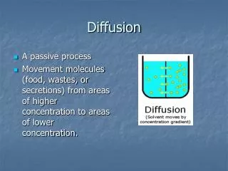
Payload Summary We will investigate the effects of acceleration and vibrations during flight on the diffusion of dye into liquids using digital imaging.
Payload Objectives • Determine the effect of acceleration on the diffusion of dye into liquids • Determine the effect of vibrations on the diffusion of dye into liquids
Payload Success Criteria • Collected data from the camera and accelerometers is accurate • Vessels containing liquid do not leak • Dye is injected into the liquid correctly • Images from camera are received • Acceleration is recorded • Payload is recovered
Payload Assembly Syringe Battery Sealed Plexiglas vessel LED Syringe Camera Sealed petri dish Camera LED Battery
Nikon AW100 Camera • Selection Rationale • Fits inside the payload chamber • Waterproof (in case of payload damage) • Minimum focus is 1cm (0.4”) • Full HD video 1920 x 1080 @ 30fps • Sufficient memory/battery capacity • Within the budget of our project ($300) • Robust design (designed for extreme sports)
Integration of Payload Modules Bulkhead Coupler Tube Rocket Body
Experiment Sequence Launch and Boost • Dye is injected into the solution • Camcorder records the diffusion process The experiment chamber is brightly lit using LEDs to prevent any exposure problems during recording
Experiment Sequence Coast and Apogee The camcorder continues to record the diffusion process until the vehicle reaches apogee. Accelerometer records acceleration data.
Experiment Sequence Data Analysis The pictures taken during the flight are analyzed
Controls • Preflight ground tests • Pictures of Petri dish from overhead camcorder • Water tank pictures from side view Control Group (stationary) Experimental Group
Variables • Independent variables a Acceleration t Time after dye is released (flight time) • Dependent Variables R Rate of diffusion (diffusion front speed) P Pattern of diffusion (qualitative classification)
Correlations • R = f(a) Rate of diffusion in relation to acceleration • R = f(t) Rate of diffusion in relation to time after dye isreleased • P = f(a) Pattern of diffusion in relation to acceleration • P = f(t) Pattern of diffusion in relation to time after dye is released
Image Analysis Voids Measure color saturation in each pixel Boundary rectangle: X pixels by Y pixels
Image Analysis To quantify the results of our experiment, we have selected the following characteristics to measure. Computerized digital image analysis will be used and we expect to process over 7 billion pixels using a multicore Linux machine.
Instrumentation and Measurement • We will use commercially available accelerometers and altimeters • The sensors will be calibrated • We will do extensive testing on the ground prior to the rocket launch