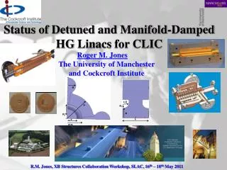
Progress on Damped and Detuned Accelerating Structures
Progress on Damped and Detuned Accelerating Structures. A . D’Elia 1,2,3 , I . Nesmiyan 1,2 , R. M. Jones 1,2. 1 School of Physics and Astronomy, University of Manchester, Manchester, United Kingdom 2 The Cockcroft Institute, Cheshire, United Kingdom 3 CERN, Geneva, Switzerland.


Progress on Damped and Detuned Accelerating Structures
E N D
Presentation Transcript
Progress on Damped and Detuned Accelerating Structures A. D’Elia1,2,3, I. Nesmiyan1,2, R. M. Jones1,2 1School of Physics and Astronomy, University of Manchester, Manchester, United Kingdom 2The Cockcroft Institute, Cheshire, United Kingdom 3CERN, Geneva, Switzerland https://indico.cern.ch/event/301619/ a https://indico.cern.ch/event/301619/ 1
Overview of WP 12.3.1 • Introduction to LCs and High Gradient Acceleration: Self-induced wakefields& breakdown on cavity surface due e.m. fields • Baseline CLIC design and alternate linacstructures:Heavy damped (CLIC_G), Choke suppression, Damped and Detuned (DDS)
I. CLIC –Overall Layout -3 TeV Drive Beam Generation Complex Drive beam Main beam Main Beam Generation Complex
Effect of Breakdown Observed in Damped Detuned Structures (DDS) • Input end indicated worst damage • Prompted a major programme to investigate means to mitigate for this • Shorter structures • Lower group velocity (vg) • Standing wave (SW) structures
I. Rationale for Wakefield Suppression • Charged particle beam excites parasitic modes • Why damp these modes? • Here we discuss linear collider applications & developing light source applications - in which a train of bunches is accelerated • In order to maintain Beam Quality and to ensure BBU (Beam Break Up) resonant instabilities do not occur the modes with particularly large ‘kick factors’ must be damped
I. Features of Wakefields • Short-range wakefields~a-3.8: sets a lower limit on aperture: a ~ 0.17λ • Long-range wakefields: disrupt the trailing bunches (2820 in the present ILC design), dilute the beam emittance and can give rise to an instability known as BBU (Beam Break Up) • The driving bunch excites an EM field in the cavity which persists long after the original bunch has left the cavity. • The transverse force exerted on the trailing particles has a complicated dependence on position within the structure. However, the integral along the axis of the transverse force (Ft)is much simpler and this defines W(s), the wakefield: • Long range wakes are suppressed by careful detuning and damping. Contours indicate density of original Gaussian distrn. BBU Due to Short-Range Wakefields r s v =cez q1 q2 r1
I. Band Partitioning • Band partitioning of kick factors in 206 cell DDS1 X-band structure (facc=11.424 GHz). Largest kick factors located in the first band. Third and sixth bands although, an order of magnitude smaller, must also be be detuned along with the 1st band. • CLIC design facc =11.9942 GHz shifts the dipole bands up in frequency. • The partitioning of bands changes with phase advance. Choosing a phase advance close to π per cell results in a diminution of the kick factor of the first band and and enhancement of the 2nd and 3rd bands. A similar effect occurs close to π/2. • Kick factors versus phase advance for cells with an iris radius of ~ 4.23 mm. Ref: Jones et. al, 2003, SLAC-PUB 9467 7
II. CLIC Baseline Accelerating Structure HOM damping waveguides 11.9942 GHz, 2π/3 (8.332 mm period) Alignment High electric field and power flow region - breakdown Magnetic field concentration – pulsed surface heating Cooling Vacuum pumping Heavy Damping, Q~10. Dielectric materials impinge into structure Short range wakefields Beam and rf W. Wuensch, CERN 8
II. Introduction –Present CLIC baseline vs. alternate DDS design • The present CLIC structure relies on linear tapering of cell parameters and heavy damping with a Q of ~10. • Wake function suppression entails heavy damping through waveguides and dielectric damping materials in relatively close proximity to accelerating cells. • Choke mode suppression provides an alternative, but may negatively impact Rshand have an impact on breakdown (Jiaru Shi leads this) • Viable alternative is presented by University of Manchester’s CLIC_DDS design - parallels the DDS developed for the J/NLC (Japanese/Next Linear Collider), and entails: 1. Detuning the dipole bands by forcing the cell parameters to have a precise spread in the frequencies –presently Gaussian Kdn/df- and interleaving frequencies of adjacent structures. 2. Moderate damping Q ~ 500-1000 9
II. C-Band Choke Mode HOM Suppression SPring-8 (Super Photon ring-8GeV) • Synchrotron radiation facility, including compact SASE Source in Japan • High peak-brilliance soft X-ray FEL project for R&D A • Angstrom X-ray laser facility. • SCSS (SPring-8 Compact SASE Source)will provide six order of magnitude peak-brilliance enhancement compared to the current third-generation sources at 3 ~ 20 nm • C-Band (5.712 GHz) linacs provided with choke mode damping • HOMs flow out through radial channels • Fundamental mode trapped within the structure (λ/4) • 35-40 MeV/m Ref: 1. R. M. Jones, Wake field Suppression in High Gradient Linacs for Lepton Linear Colliders, Phys. Rev. ST Accel. Beams 12, 104801, 2009. 2. http://www-xfel.spring8.or.jp 3. T. Shintake, Japanese J.Appl.Phys.31:L1567-L1570 (1992) 10
II. Features of CLIC DDS Linac Acceleration cells Beam tube Manifold HOM coupler High power rf coupler • NLC/GLC SLAC/KEK RDDS structure (left ) illustrates the essential features of the conceptual design • Each of the cells is tapered –iris reduces (with an erf-like distribution –although not unique) • HOM manifold running alongside main structure removes dipole radiation and damps at remote location (4 in total) • Each of the HOM manifolds can be instrumented to allow: 1) Beam Position Monitoring2) Cell alignments to be inferred H60VG4SL17A/B -2 structure interleaved RF (Power min) • CMM (Coordinate Measurement Machine) data compared to ASSET power minimisation data remapped to frequency • Dots indicate power minimisation CMM Exp. Measurement Prediction Remote Cell Alignment Diagnostic Wake Suppression 11
II. Prediction Based on Circuit Model of DDS **Wakefield damping in a pair of X-band accelerators for linear colliders.R.M. Jones , et al, Phys.Rev.ST Accel.Beams 9:102001,2006. 12
II. Summary of GLC/NLC ExpvsCctModel Qcu DS ASSET Data RDDS1 DDS3 (inc 10MHz rms errors) DDS1 H60VG4SL17A/B -2 structure interleaved RDDS1 Conspectus of GLC/NLC Wake Function Prediction and Exp. Measurement (ASSET dots) Refs: 1. R.M. Jones,et al, New J.Phys.11:033013,2009. 2. R.M. Jones et al., Phys.Rev.STAccel. Beams 9:102001, 2006. 3. R.M. Jones, Phys.Rev.STAccel. Beams, Oct.,2009. 13 13
Accelerator Structure Setup (ASSET) II. Measurement of Wakefields/HOMs • Electron bunch serves as the witness bunch • In traversing the DUT, the witness bunch is deflected by the wake function generated by the positron drive bunch. • Witness bunch passes though chicane and down linac where trajectory is recorded by BPMs • The transverse wake function is determined by measuring the change in the witness bunch deflection per unit change in the drive bunch offset in the structure. • W┴ is the transverse wake function at time t behind the drive bunch, Ew (~ 1.2 GeV) is the witness bunch energy and Δydis the offset in the drive bunch from the electrical centre of the accelerating structure. • Wake function units are transverse voltage per drive charge (end), drive offset and structure length (Ls), and • Angular kick imparted to the witness bunch is found from ratio of the transverse to longitudinal energy: Ref: R. M. Jones, Wake field Suppression in High Gradient Linacs for Lepton Linear Colliders, Phys. Rev. ST Accel. Beams 12, 104801, 2009
II. CLIC Design Constraints 1) RF breakdown constraint 2) Pulsed surface temperature heating 3) Breakdown Factor • Beam dynamics constraints • For a given structure, no. of particles per bunch N is decided by the <a>/λ and Δa/<a> • Maximum allowed wake on the first trailing bunch • Wake experienced by successive bunches must also be below this criterion Ref: Grudiev and Wuensch, Design of an x-band accelerating structure for the CLIC main linacs, LINAC08 15
II. Initial CLIC_DDS Design –Δfdetermination Bandwidth Variation σ Variation Lowest dipole ∆f ~ 1GHz Q~ 10 => CLIC_DDS Uncoupled Design CLIC_G
II. Structure Geometry: Cell Parameters Structure GeometryCell parameters Iris radius Iris radius R amin, amax= 4.0, 2.13 b t/2 Cavity radius Cavity radius a1 Rc a bmin, bmax= 10.5, 9.53 a Fully Interleaved 8-structures Sparse Sampled HPT (High Power Test) a+a1 L 17
II. Summary of CLIC_DDS_C Dipole mode Manifold mode Manifold ∆f=3.6 σ =2.3 GHz ∆f/fc=13.75% Coupling slot 24 cells No interleaving Meets design Criterion? ∆fmin = 8.12 MHz ∆tmax =123 ns ∆s = 36.92 m ∆fmin = 65 MHz ∆tmax =15.38 ns ∆s = 4.61 m 192 cells 8-fold interleaving 192 cells 8-fold interleaving
II CLIC_DDS_E Elliptical Design –E Fields b a Circular Square Single undamped cell Iris radius=4.0 mm Convex ellipticity
II. Beam Dynamics • Direct Effect • Assumes bunches are effected one- on-one –usual assumption for several years. • a is a matrix which describes the wake • In addition for CLIC_G, Q ~ 10 and this effectively enables Wtto be neglected after nearest neighbours • Indirect Effect • Assumes bunches are influenced by succeeding bunches –many bunch coupling Ref: D. Schulte: PAC09, FR5RFP055; PRST-AB 14,084402 (2011)
II. Beam Dynamics • Indirect Effect • Straightforward to build this up in an iterative process for m bunches–each bunches communicates with its neighbour and this ripples down the chain • Figures of merit:Fc representative of coherent oscillations of the train -the rms over the whole trainFrms the bunch to bunch rms
II. Tracking Simulations Inc. Realistic Bunch & Machine Parameters
II. Tracking Simulations Inc. Realistic Bunch & Machine Parameters
II. General Features of CLIC_DDS_A 12 GHz DDS A. General information • General design features • RF Disks stack • VDL • - 24 regular cells • 2 matching cells • Input and output cells • KEK • - 24 regular cells • 2 matching cells (comprised of 3 disks) • Input and output cells (each comprised of 2 disks) • Mode Launcher couplers (VDL and KEK) • “Push-Pull” tuning system (VDL and KEK) • - 4 tuning studs brazed inside each RF disk • Cooling system (VDL and KEK) • 2 parallel cooling circuits • 2 twin cooling blocks 12 GHz DDS A, 3D-view Vacuum Flange Beam Pipe Cooling Tube RF Flange Coupler RF Disk Stack Cooling Block Tuning stud Regular RF disk. Three-quarter view Courtesy G. Riddone, V. Soldatov
First Comparison Between KEK Measurements& Simulations on Morikawa Cells Discs * HFSS scaled in air using εr=1.000618 §This cell is the actual one –non-symmetrical and equipped with an averaging of b. This explains the difference in the frequency from the nominal value of 11994.6MHz Indicative of ~2 μm fab tolerance! Tuning range ~20MHz
Full Structure S21 Measurement • Overall Status • Complete CLIC_DDS_A has been diffusion bonded at Bodycoat. • Brazing of cooling block (blocks, tubes and caps) is complete • Tuning studs recently brazed (tuned in Feb 2014) • Structure will be high-power tested at CERN in 2014 (last quarter?) to assess ability to sustain high gradients ~5MHz tuning needed
S11 Measured Prior to Tuning (Feb 2014) Reflection at the input Reflection at the output 28
S11 Measured Afer Tuning (Feb 2014) Reflection at the output Reflection at the input 29
II. Final Remarks Conclusions and future steps • A CLIC_G baseline structure has met breakdown parameters in unloaded conditions. • Compact DDS provides efficient wakefield damping for linear collider and light source applications -with reduced and de-localized loads • Built-in BPM facility of HOMs in DDS provide a unique means of tracking beam and structure alignment. Also, DDS requires less loads than CLIC_G (requires loads either end rather than at each cell) • Mechanical design takeainto account all requirements on RF, beam physics, machining, assembly, installation and operation • Beam Dynamics simulation indicate that errors introduced in fabricating 140,000 structures provides randomization which aids in preservation of beam quality (emittance dilution minimised) • Chokemode structure provides an efficient means of suppressing HOMs • Fruitful collaboration with several institutes has been established and it is essential to develop X-band RF structure production technology • Single structure has recently (Feb 2014) been tuned in readiness for high power/gradient testing
II. Resource on HG Structures • Collation of selected papers from:X-band structures, beam dynamics and sources workshop (XB-10) Nuclear Instruments and Methods in Physics Research, Section A: Accelerators, Spectrometers, Detectors and Associated Equipment • - Special volume devoted to X-Band Accelerators:Volume 657, Issue 1, 21 November 2011, Eds, Chattopadhyay, S., Jones, R.M. • (http://www.sciencedirect.com/science/journal/01689002/657/1) Selected Pubs R. M. Jones, et. al, PRST-AB, 9, 102001, 2006. V. F. Khan and R.M. Jones, EPAC08, 2008. V. F. Khan and R.M. Jones, LINAC08, 2008. V. F. Khan and R.M. Jones, Proceedings of XB08, 2008. R. M. Jones, PRST-AB, 12, 104801, 2009. R. M. Jones, et. al, NJP, 11, 033013, 2009. V. F. Khan and R.M. Jones, PAC09, 2009. V. F. Khan, et. al, IPAC10, 2010. V. F. Khan, et. al, LINAC10, 2010. R.M. Jones, NIMA, 2011. V.F. Khan et. al, NIMA, 2011., Ph.D.Thesis, 2011
Final Remarks on HG Structures • CLIC_G, DDS and Choke mode-based wakefield suppression structures are relatively mature –although considerable experimental verification is needed: • The baseline design, CLIC_G provides heavy damping (Q~10) of every cell in which dielectrics are located in immediate vicinity of coupling slots. • Choke mode suppression has some impact on fundamental mode Q and also some potential for higher order mode issues. Relatively simple to fabricate. • DDS allows remote location of (reduced) HOM loads. Built-in BPM and structure diagnostic. Sensitivity to fabrication errors –randomisation helps. Less rf loads needed (~22 less per 22 cell cavity)