Download

1 / 69
700 likes | 849 Views
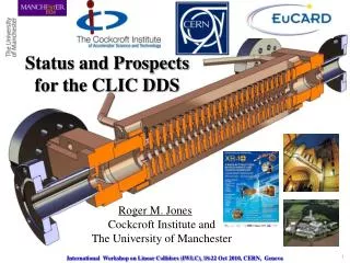
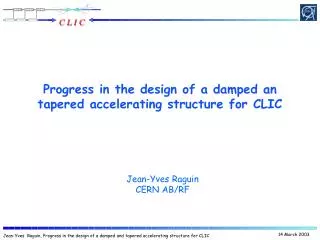
Status of Detuned and Manifold-Damped HG Linacs for CLIC. Roger M. Jones The University of Manchester and Cockcroft Institute. R. t/2. b. a 1. a. R c. L. a. a. a+a 1. R.M. Jones, XB Structures Collaboration Workshop, SLAC, 16 th – 18 th May 2011. Overview.

E N D
Status of Detuned and Manifold-Damped HG Linacs for CLIC Roger M. JonesThe University of Manchester and Cockcroft Institute R t/2 b a1 a Rc L a a a+a1 R.M. Jones, XB Structures Collaboration Workshop, SLAC, 16th – 18th May 2011
Overview • Brief overview of some features of DDS • Multi-functional manifolds • Summary of measurements…) • Expected tolerance sensitivities • Status of CLIC_DDS_A design • Its taken from the fully-interleaved wakefield • Brief summary of issues (mechanical electrical considerations) that went into finalising it. • Final remarks • Open questions (KEK machining needs ..) • Ongoing work (Fully equipped structure: CLIC_DDS_B)
1. Features of Wakefields Contours indicate density of Gaussian distrn. Transverse momentum kick:
1. Band Partitioning • Band partitioning of kick factors in 206 cell DDS1 X-band structure (facc=11.424 GHz). Largest kick factors located in the first band. Third and sixth bands although, an order of magnitude smaller, must also be be detuned along with the 1st band. • CLIC design facc =11.9942 GHz shifts the dipole bands up in frequency. • The partitioning of bands changes with phase advance. Choosing a phase advance close to pi per cell results in a diminution of the kick factor of the first band and and enhancement of the 2nd and 3rd bands. A similar effect occurs close to /2. • Kick factors versus phase advance for cells with an iris radius of ~ 4.23 mm. Ref: Jones et. al, 2003, SLAC-PUB 9467
1. Review of General Methods of Wake-Field Damping Strong Damping (Q~10) => some loss in the shunt impedance of the monopole mode. Magnetic coupling –azimithal slots (kidney slots) Electric coupling – longitudinal slots 2. Resonant suppression single frequency: fdipole = (n/2) fbunch (zero-mode crossing) multiple frequency, beat-note: fdipole1 – fdipole2 = n fbunch 3. Non-resonant suppression –Detuning Rectangular Kdn/df (kick factor weighted mode density) => sinc function wake Gaussian Kdn/df => Gaussian wake function Truncation of Gaussian necessitates light damping in addition to detuning Less sensitivity to frequency errors Less impact on fundamental mode shunt impedance
1. General Aspects of Detuning Gaussian density distributions • Kick factor weighted density function: Kdn/f ~ exp[-(-0)2/2 2] • Ideally: W(t) ~ exp(- 2 t2/2) • Advantages over other methods • It is non-resonant and hence it does not freeze collider operation a bunch spacing other than the minimum bunch spacing. • Wakefield decreases rapidly and monotonically • It permits an error function interpolation with relatively sparse parameters • Disadvantages • Gaussian distribution is not limited and thus eventually it is truncated. This truncation gives rise to a sinc-like (=sin(x)/x) wake which curtails the rapid fall-off at a level dependent on the truncation point • The finite number of cells => finite number of modes => partial recoherence of wake-field starting at a time t ~ 1/fmax (where fmax is the maximum separation of modes). Also, with damping there is another coherence point, further out, at 1/ fmin (where fmin is the minimum separation of modes, which lies in the centre of the Gaussian)
1. (R)DDS HIGHLIGHTS: Features and Achievements/Lessons • Testament to fruitful collaboration (over a decade or more) in the NLC/JLC programme (SLAC, KEK, FNAL, LLNL). • One slide summary of all wakefield measurments!
1. Measurement of Wakefields/HOMs • Electron bunch serves as the witness bunch • In traversing the DUT, the witness bunch is deflected by the wake function generated by the positron drive bunch. • Witness bunch passes though chicane and down linac where trajectory is recorded by BPMs • The transverse wake function is determined by measuring the change in the witness bunch deflection per unit change in the drive bunch offset in the structure. • W┴ is the transverse wake function at time t behind the drive bunch, Ew (~ 1.2 GeV) is the witness bunch energy and yd is the offset in the drive bunch from the electrical centre of the accelerating structure. • Wake function units are transverse voltage per drive charge (end), drive offset and structure length (Ls), and • Angular kick imparted to the witness bunch is found from ratio of the transverse to longitudinal energy: Ref: R. M. Jones, Wake field Suppression in High Gradient Linacs for Lepton Linear Colliders, Phys. Rev. ST Accel. Beams 12, 104801, 2009
1. GLC/NLC Exp vs Cct Model Wake Qcu DS ASSET Data RDDS1 DDS3 (inc 10MHz rms errors) DDS1 Special case:: Random errors added to mode freqs to fit exp. data H60VG4SL17A/B -2 structure interleaved RDDS1 Conspectus of GLC/NLC Wake Function Prediction and Experimental Measurement (ASSET dots) Refs: 1. R.M. Jones,et al, New J.Phys.11:033013,2009. 2. R.M. Jones et al., Phys.Rev.ST Accel. Beams 9:102001, 2006. 3. R.M. Jones, Phys.Rev.ST Accel. Beams, Oct.,2009. 10
1. Impact of Fabrication Errors on Wakefield Suppression in RDDS1 Kdn/df and Mode Spacing Wakefield Experienced by Bunches Frequency Errors
1. Determination of HOMs in Structure via Stretched Wire Measurement • Illustrated is an X-band Set-up at SLAC. • Designed as part of the GLC/NLC programme. • Able to accommodate 1.8m structures. • Several other configurations in use internationally. • Trapped modes not readily accessible (hence beam- • -based verification of simulations needed) Ref: F. Caspers, Bench methods for beam-coupling impedance measurement (Lecture notes in beams: intensity limitations vol 400) (Berlin, Springer, 1992) 12
1. Verification of Synchronous Frequencies from Measurement of Cell Stacks
1. Determination of Cell Offset From Energy Radiated Through Manifolds RF (Power min) CMM
1. Summary of NLC/GLC Wakefield Damping • Detuning along with moderate damping has been shown to be well-predicted by the circuit model. • Interleaving of successive structures allows the detuning to be effective. • Manifold wakefield suppression has added benefits: • Serves as built-in beam diagnostic • Allows internal alignment of cells to be obtained from manifold radiation • Serves as vacuum pump-outs.
2. X-Band Wake-field Suppression for CLIC CLIC_DDS_A & CLIC_DDS_B 18
2. Wake Function Suppression for CLIC -Staff 2. FP420 –RF Staff • Roger M. Jones (Univ. of Manchester faculty) • Alessandro D’Elia (Dec 2008, Univ. of Manchester PDRA based at CERN) • Vasim Khan (PhD student, Sept 2007) • Nick Shipman (PhD student Sept 2010, largely focused on breakdown studies) • Part of EuCARD ( European Coordination for Accelerator Research and Development) FP7 NCLinac Task 9.2 • Major Collaborators: W. Wuensch, A. Grudiev, I. Syrachev, R. Zennaro, G. Riddone (CERN) V. Khan, CI/Univ. of Manchester Ph.D. student graduated April 2011 (now CERN Fellow) A. D’Elia, CI/Univ. of Manchester PDRA based at CERN (former CERN Fellow). N. Shipman, CERN/CI/Univ. of Manchester Ph.D. student L. Carver Sept 2011 CI/Univ. of Manchester Ph.D. student 19
2. Introduction –Present CLIC baseline vs. alternate DDS design • The present CLIC structure relies on linear tapering of cell parameters and heavy damping with a Q of ~10. • Wake suppression is effected through waveguides and dielectric damping materials in relatively close proximity to accelerating cells. • Choke mode suppression provides an alternative, but as shown for SW (V. Dolgashev et al), it will negatively impact Rsh -planned TW structures are worth investigating though (talk by J. Shi?) • A viable alternative is presented by our CLIC_DDS design - parallels the DDS developed for the GLC/NLC, and entails: 1. Detuning the dipole bands by forcing the cell parameters to have a precise spread in the frequencies –presently Gaussian Kdn/df- and interleaving the frequencies of adjacent structures. 2. Moderate damping Q ~ 500-1000 20
2. Current CLIC Baseline Accelerating Structure HOM damping waveguides 11.9942 GHz, 2π/3 with a 8.332 mm period Alignment High electric field and power flow region - breakdown Magnetic field concentration – pulsed surface heating Cooling Vacuum pumping Short range wakefields Beam and RF EPAC, 26 June 2008 W. Wuensch, CERN
2. CLIC Design Constraints • Beam dynamics constraints • For a given structure, no. of particles per bunch N is decided by the <a>/λ and Δa/<a> • Maximum allowed wake on the first trailing bunch • Wake experienced by successive bunches must also be below this criterion 1) RF breakdown constraint 2) Pulsed surface temperature heating 3) Cost factor Ref: A. Grudiev and W. Wuensch, Design of an x-band accelerating structure for the CLIC main linacs, LINAC08 22
2. Initial CLIC_DDS Designs Three designs Initial investigation of required bandwidth to damp all bunches (~3GHz) –succeeds to suppress wakes, fails breakdown criteria! New design, closely tied to CLIC_G (similar iris a), necessitates a bandwidth of ~ 1 GHz. Geometry modified to hit bunch zero crossings in the wakefield -succeeds from breakdown perspective, tight tolerances necessary to suppress wakes! Relaxed parameters, modify bunch spacing from 6 to 8 rf cycles and modify bunch population. Wake well-suppressed and satisfies surface field constraints. CLIC_DDS_C (f ~ 3.6, 13.75%) –SUCCESS (on suppressing wakes and meeting breakdown criteria) Three designs Initial investigation of required bandwidth to damp all bunches (~3GHz) –succeeds to suppress wakes, fails breakdown criteria! Three designs Initial investigation of required bandwidth to damp all bunches (~3GHz) –succeeds to suppress wakes, fails breakdown criteria! New design, closely tied to CLIC_G (similar iris a), necessitates a bandwidth of ~ 1 GHz. Geometry modified to hit bunch zero crossings in the wakefield -succeeds from breakdown perspective, tight tolerances necessary to suppress wakes! 23
2. Initial CLIC_DDS Design –f determination Bandwidth Variation Variation Lowest dipole ∆f ~ 1GHz Q~ 10 CLIC_DDS Uncoupled Design CLIC_G
2 Relaxed parameters tied to surface field constraints (f/<f> = 13.75 %) Uncoupled parameters Cct Model Including Manifold-Coupling Cell 1 Cell 24 • Iris radius = 4.0 mm • Iris thickness = 4.0 mm , • ellipticity = 1 • Q = 4771 • R’/Q = 11,640 Ω/m • vg/c = 2.13 %c • Iris radius = 2.13 mm • Iris thickness = 0.7 mm, • ellipticity = 2 • Q = 6355 • R’/Q = 20,090 Ω/m • vg/c = 0.9 %c • Employed spectral function and cct model, including Manifold-Coupling, to calculate overall wakefunction. 25
2. Structure Geometry: Cell Parameters Structure GeometryCell parameters Iris radius Iris radius R amin, amax= 4.0, 2.13 b t/2 Cavity radius Cavity radius a1 Rc a bmin, bmax= 10.5, 9.53 a Fully Interleaved 8-structures Sparse Sampled HPT (High Power Test) a+a1 L 26
2. Relaxed parameters –full cct model Coupled 3rd mode Coupled 3rd mode Uncoupled 2nd mode Uncoupled 2nd mode Uncoupled 1st mode Uncoupled 1st mode Avoided crossing Avoided crossing Uncoupled manifold mode Light line Light line Uncoupled manifold mode Uncoupled 2nd mode Coupled 3rd mode Uncoupled 1st mode Avoided crossing Light line Uncoupled manifold mode Mid-Cell First Cell • Dispersion curves for select cells are displayed (red used in fits, black reflects accuracy of model) • Provided the fits to the lower dipole are accurate, the wake function will be well-represented • Spacing of avoided crossing (inset) provides an indication of the degree of coupling (damping Q) End Cell 27
2. Summary of CLIC_DDS_C Dipole mode Manifold mode Manifold ∆f=3.6 σ =2.3 GHz ∆f/fc=13.75% Coupling slot 24 cells No interleaving Meets design Criterion? ∆fmin = 8.12 MHz ∆tmax =123 ns ∆s = 36.92 m ∆fmin = 65 MHz ∆tmax =15.38 ns ∆s = 4.61 m 192 cells 8-fold interleaving 192 cells 8-fold interleaving
2. CLIC_DDS_E • Enhanced H-field on various cavity contours results in unacceptable T (~65 K). • Can the fields be redistributed such that a ~20% rise in the slot region is within acceptable bounds? • Modify cavity wall • Explore various ellipticities (R. Zennaro, A. D’Elia, V. Khan)
2. CLIC_DDS_E Elliptical Design –E Fields Circular Square Single undamped cell Iris radius=4.0 mm Convex ellipticity Concave ellipticity ε=-8.28 ε=-2.07 ε=-4.14
2. CLIC_DDS_E Elliptical Design, Single Undamped Cell Dependence of Fields on Iris radius = 4.0 mm Iris thickness = 4.0 mm Chosen design
2. CLIC_DDS_E Single-Cell Surface Field Dependence on ε Optimisation of cavity shape for min • Iris radius ~4mm. For both geometries • Averaging surface H over contour =1.38 Rectangular ( =∞) Circular ( =1) Circular cell ε=1.38 ε=0.82 ε =0.82 Manifold-damped single cell ε=1.38 ε=0.41 Optimised parameters for DDS2 ε=2.07 ε=4.14 Undamped cell See WG talk by Vasim Khan
2. CLIC_DDS_E, Optimisation of: , ∆f and Efficiency Efficiency ∆T • Optimisation of parameters based on manifold damped structures. • Vary half-iris thickness. • 3-cell simulations, with intermediate parameters obtained via interpolation. • Choose parameters with minimal surface E-field, pulse temperature rise, and adequate efficiency. Pin ∆f dipole Chosen optimisation (CLIC_DDS_E)
2. CLIC_DDS_E: Detailed Geometry r2 Radius = 0.5 mm h1 2*r2 r1 a2 h g=L - t r1 r1+h+2r2 a1 Rc t= 2a2 a L
2. Impact on Parameters: CLIC_DDS_C to CLIC_DDS_E DDS2_E DDS1_C DDS1_C DDS2_E
2. CLIC_DDS_E -Fundamental Mode Parameters DDS1_C DDS_E DDS_E Vg Q DDS1_C R/Q DDS1_C DDS1_C DDS_E DDS_E • Group velocity is reduced due increased iris thickness • R/Q reduced slightly • Surface field and T reduced significantly by using elliptical cells DDS1_C Es Hs DDS_E
2. Wake Function for CLIC_DDS_E -Dipole Circuit Parameters DDS_C DDS_E Cct DDS_C DDS_E DDS_E DDS1_C • Avoided crossing x is significantly reduced due to the smaller penetration of the manifold. • Some re-optimisation could improve this Avoided Crossing ∆f=3.5 σ =2.2 GHz ∆f/fc=13.75% a1=4mm a24=2.3mm
2. Consequences on Wake Function Spectral Function Wake Function DDS1_C DDS2_E
2. CLIC_DDS_E: Modified Design Based on Engineering Considerations DDS2_ER DDS2_E Rounding necessitates reducing this length (moves up) Rc Rounding • To facilitate machining of indicated sections, roundings are introduced (A. Grudiev, A. D’Elia). • In order to accommodate this, Rc needs to be increased DDS2_ER. • Coupling of dipole modes is reduced and wake-suppression is degraded. How much?
Cell # 1 Uncoupled Dipole mode Uncoupled manifold mode Cell # 24 2. CLIC_DDS_ER Dispersion Curves Uncoupled 2nd Dipole Mode Cell # 1 Avoided crossing Light Line Light line Cell # 24
4. CLIC_DDS_E vs CLIC_DDS_ER Wakefield Spectral Function Wakefunction CLIC_DDS_E :Rc=6.2 - 6.8 mm (optimised penetration) • CLIC_DDS_ER : Rc=6.8 mm const (a single one of these structures constitutes CLIC_DDS_A, being built for HP testing) • Wakefield suppression is degraded but still within acceptable limits.
2. CLIC_DDS_A: Structure Suitable for High Power Testing • Info. on the ability of the 8-fold interleaved structure to sustain high e.m. fields and sufficient T can be assessed with a single structure. • Single structure fabricated in 2010/1st quarter 2011, CLIC_DDS_A, to fit into the schedule of breakdown tests at CERN. • Design is based on CLIC_DDS_ER • To facilitate a rapid design, the HOM couplers have been dispensed with in this prototype. • Mode launcher design utilised • SRF design complete! • Mechanical drawings, full engineering design completed! • Qualification end cells fabricated. Received Oct 15 2010 from VDL (Netherlands)
2. CLIC_DDS_A Parameters Esur Max. Values Esur=220 MV/m ∆T = 51 K Pin= 70.8 Eacc_UL=131 MV/m Sc=6.75 W/μm2 RF-beam-eff=23.5% 35*Sc Eacc Pin ∆T CLIC_G Values Esur=240 MV/m ∆T = 51 deg. Pin= 63.8 Eacc_UL=128 MV/m Sc=5.4 W/μm2 RF-beam-eff=27.7% Dashed curves : Unloaded condition Solid curves: Beam loaded condition
2. CLIC_DDS_A Wake 24 cells No interleaving • Wake of a non-interleaved 24 cell structure –first structure of 8-fold interleaved structure chosen. • Motivated by high gradient testing • Wake is measurable and provides a useful comparison to simulations (but will not, of course, meet beam dynamics criteria) • FACET (revive ASSET?) tests of wake? Undamped Qavg ~1700 Damped 24 cells No interleaving
2. CLIC_DDS_A Wake • Recent simulations with GdfidL (finite difference based code) • Single structure simulated • GdfidL simulations do not include the loading of the dipole mode by the fundaments, coupler (Q~36) • Nonetheless, reasonable agreement with circuit model and damping is expected to be sufficient Cct model GdfidL • First comparison of cct model vs GdfidL for CLIC_DDS
2. Matching CLIC_DDS_A I/P • Firstly, match-out either end of structure with regular cells: • Structure for test will utilise a mode launcher • Initially, simulate a structure with one regular cell and two matching cells at either end and we study the minima in S11 as a function of the geometrical parameters of the matching cells (a, L –adopt L variation, rather than b, from space considerations) • Add additional (2, then 3) identical standard cells (const. imp) and follow the same procedure and modify parameters of matching cells to minimise S11 • The matching condition (on a, L) is that which coincident with all 3 simulations. • Secondly, once complete, match-out the full, tapered structure based on this match.
2. CLIC_DDS_A Axial E-Field Surface E-Field E-field Port11 Port 2 7.5 Beam 7 Matching cell Ez (V/m x104) Es (V/m x104) 5.0 0 300 0 z (mm) 225 z (mm) • Match-out the full, tapered structure • E-field and S11 shown ~198.6mm
S12 S22 2. CLIC_DDS_A S Params Q 11.988 12 S11 -48.2dB@ 11.9944GHz 0dB -50dB /2 (GHz) 6165 @ 11.9944GHz
2. Mechanical Eng. Design of DDS_A Water pipes for cooling Vacuum flange Power output Tuning holes • Non-interleaved 24 cell structure –first structure of 8-fold interleaved structure chosen. • High power (~71MW I/P) and high gradient testing • To simplify mechanical fabrication, uniform manifold penetration chosen Power input Cutaway-view Beam V.Soldatov, CERN