Download

1 / 14
140 likes | 280 Views
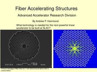
Design and objectives of test accelerating structures. Riccardo Zennaro. 11.4 GHz test structures 8 new designs in 2007 and 17 new structures. 30 GHz test structures 8 new designs in 2007 and 12 new structures. Test of CLIC structure prototype (vg1)

E N D
Design and objectives of test accelerating structures Riccardo Zennaro
11.4 GHz test structures8 new designs in 2007 and 17 new structures 30 GHz test structures8 new designs in 2007 and 12 new structures Test of CLIC structure prototype (vg1) Test of different geometries (aperture and iris thickness) Test of P/c Comparison of damped and undamped structures Comparison of technology: quadrant to disk Test of different geometries (aperture and iris thickness) Test of P/c Comparison of damped and undamped structures Comparison of technology: quadrant to disk Test of different materials Test of different cleaning procedures Test of new ideas
The CLIC vg1: CLIC prototype Collaboration between CERN,KEK,SLAC 8 structures, 4 different designs
Comparison of damped and undamped structures and technology The vg1 family: T18_vg2.4_disk TD18_vg2.4_disk T18_vg2.4_quad TD18_vg2.4_quad 30 GHz C30_vg_4.7_quad C30_vg_4.7_disk (tested) HDS_4_thick NDS_4_thick HDS: hybrid damping Direct comparison of technology (quadrant/disk) Direct comparison of dumped/undamped structures
Different geometries (all structures in disks) In red: 11.4 GHz new structures In blue: 30 GHz new structures (scaled values for a and d) (*) not very different from input vg1 (d=2.79; a=4.06)
Direct comparison of variation of a and P/c In red: 11.4 GHz new structures In blue: 30 GHz new structures (scaled values for a and d)
Direct comparison of variation of d In red: 11.4 GHz new structures In blue: 30 GHz new structures (scaled values for a and d) (*) not very different from input vg1 (d=2.79; a=4.06)
Direct comparison of variation of P/c In blue: 30 GHz new structures (scaled values for a and d) (*) different phase advance (90˚)
TM02 structure Is it possible to change some global parameter without changing local field distribution? Only by changing the propagating mode TM01 regular cell “reference” Same phase advance Same P/c Same aperture and iris shape Same field configuration in the iris region but Different group velocity: 4.7% & 2% Different R/Q: 29 kΩ/m & 12 kΩ/m TM02 regular cell Test structure in disks: 30 cell and identical mode launcher of the “conventional” 2π/3 Ø 3.5 mm
Vg TM01: 2π/3 Vg=4.7% d a TM02: 2π/3 Vg=2.0% Direct comparison of Vg
Why speed bump? From Igor’s presentation at the X band workshop: Very often we do observe, that after accelerating structure processing the most of the surface modifications take place in a few first cells. Also the number of cells involved is correlated with the group velocity, the less the Vg the fewer cells modified. What do we certainly know, the breakdown ignition is a very fast process: 0.1 -10 ns. If so, one can propose the main difference between the “first” and “second” cell is accessible bandwidth. And the lower group velocity the more the difference. The first cell, if breakdown occurs is loaded by the input coupler/waveguide and is very specific in terms of bandwidth. Other words, the first cell can accept “more” energy during breakdown initiation then consequent ones. Worse to mention that we do not know the exact transient behavior of the breakdown and the structure bandwidth could play important role. We can tray by reducing vg in the matching cell PINC PINC HDS 60 L HDS 60 S
R=14.398 mm R_iris= 2.428 mm Iris_thickness= 1mm Speed bump (TM03) Test structure in disks: 30 cell and identical mode launcher of the “conventional” 2π/3 Ø 3.5 mm
Comparison of different materials and cleaning procedure (all 30 GHz structures in quadrants with damping waveguides) HDS11_small_Ti (Titanium) HDS11_small_Mo (Molybdenum) HDS4_vg2.6_Thick (no cleaning) HDS4_vg2.6_Thick (cleaning in Saclay) Cleaning provided by high pressure water flow (25,50,85 bars) HDS11_small_Cu (copper) Direct comparison of material Direct comparison of cleaning procedure
Conclusions • The test structure program intends to investigate the response of the b.d. rate to several free parameters that define a TW structure • In particular the following parameters are presently under investigation: • aperture • iris thickness • iris shape (elliptical) • group velocity • material • technology (quadrant/disk) • damping waveguide • If possibleonlyone parameter at the time is modified • The performances of the different structures are compared in the same power test conditions (other dynamic parameters play a fundamental rule in the b.d. rate…but this is another story) • The tests provide information not only for the b.d. rate but also in term of b.d. damage (example titanium) and b.d. damage distribution (example: speed bump) • The tests provide information on the different companies that machine the structures • For more information: riccardo.zennaro@cern.ch TM02 test