Download
1 / 23
230 likes | 381 Views
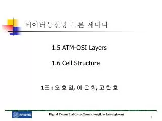
데이터통신망 특론 세미나. 1.5 ATM-OSI Layers 1.6 Cell Structure. 1 조 : 오 호 일 , 이 은 희 , 고 한 호. 1.5 ATM-OSI Layers. 기원 : 1983 년 ISO(International Standard Organization) 에서 OSI(Open System Interconnection) 라는 참조 모형을 제시 목적 : 개방형 시스템간의 통신을 위함 형태 : 계층화된 구조 (Layered Artecture)

E N D
데이터통신망 특론 세미나 1.5 ATM-OSI Layers 1.6 Cell Structure 1조 : 오 호 일, 이 은 희, 고 한 호
1.5 ATM-OSI Layers • 기원 : 1983년 ISO(International Standard Organization)에서 OSI(Open System Interconnection)라는 참조 모형을 제시 • 목적 : 개방형 시스템간의 통신을 위함 • 형태 : 계층화된 구조(Layered Artecture) • OSI standard는 어떤 종류의 network에도 적용 (circuit-switched, packet-switched technology, STM, ATM connection-oriented, connectionless mode 등)
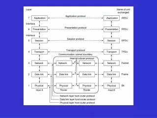
presentation layer presentation layer network layer network layer physical layer physical layer data link layer data link layer network layer session layer session layer application layer application layer transport layer transport layer data link layer physical layer VIDEO ENCODER VIDEO ENCODER HIGHER LAYERS VIDEO CODING LOWER LAYERS VIDEO NETWORKING NETWORK NODE OR GATEWAY SOURCE USER 1.5.1 Layered Artecture in OSI Standard(1) • Higher layer : host user system에 존재함 • Lower layer : network function에 관계된 계층
1.5.1 Layered Artecture in OSI Standard(2) 1. Application Layer(응용 계층) • 최상위 계층 • 네트워크를 통한 응용프로그램간의 정보교환을 담당 • 비디오 코딩의 관점 - 코딩과 전송에 앞선 과정인 비디오 포맷으로의 컨버팅과 생성이 일어나는 장소
데이터의 정보를 표현하는 방식(syntax)을 공통된 방식으로 통일 • 비디오 코딩의 관점 - 비트 rate 압축을 위한 encoding과 decoding 알고리즘을 수행하는 곳 • 손실과 에러를 감지하고 수정 비디오 코딩에서 이러한 기능은 은닉(concealment)알고리즘이라 함 • 이 계층아래에서는 더 이상 데이터의 내용은 볼 수 없다. 즉, 정보는 variable rate bit stream으로 고려된다. 1.5.1 Layered Artecture in OSI Standard(3) 2. Presentation Layer(표현 계층)
1.5.1 Layered Artecture in OSI Standard(4) 3. Session Layer(세션 계층) • 응용프로세스 사이의 매끄러운 정보교환을 위한 부가가치를 제공 • 응용프로그램간의 논리적 연결을 확립하고 관리 • 데이터 스트림의 중간중간에 검사점(check point)을 삽입 - 연결이 끊어지거나 전송에러가 발생한 경우 re-synchronization과 error recovery를 수행 • 비디오 코딩의 관점 - synchronization words의 삽입으로 frames과 segments에 해당하는 범위를 지정해주고 에러나 손실이 생겼을 때, 작업을 새로 시작할 위치 지정 • 연결 세션을 성립시키거나 해제시키는 기능을 수행
1.5.1 Layered Artecture in OSI Standard(5) 4. Transport Layer(전송 계층) • 응용프로그램의 논리적 연결과 데이터 전송을 직접 담당하는 아래 계층들을 연결하는 가교 • 네트워크를 가로지르는 메시지단위의 정보교환을 책임진다. - 통신호스트 사이의 신뢰성있는 연결(end-to-end connection)이 보장됨 • 상위 계층 응용프로그램 사이의 정보교환은 SAP(Service Access Point) 라는 주소를 통해 이루어짐 • 네트워크에 흐르는 메시지량을 조정(flow control)하고 체크섬(checksum) 방식으로 전송에러를 검출
1.5.1 Layered Artecture in OSI Standard(6) 5. Network Layer(네트워크 계층) • 이 계층에서 패킷은 라우팅, 스위칭, 멀티플렉싱 됨 • 패킷헤더에 접근하여 목적지와 에러등을 체크 • 목적 - 정보를 보내는 노드에서부터 이 정보의 목적노드까지, 전달계층에서 분할된 패킷들을 안전하게 전송하는 것
1.5.1 Layered Artecture in OSI Standard(7) 6. Data Link Layer(데이터 링크 계층) • 다음과 같은 물리적인 링크 전송서비스를 제공 - synchronization, sequence number, error detection, error correction data control 등 • 패킷이 물리계층을 통하여 곧바로 전송되도록, 패킷에 헤더(header)와 꼬리(trailer)를 덧붙여 데이터프레임(data frame)을 만든다.
1.5.1 Layered Artecture in OSI Standard(8) 7. Physical Layer(물리 계층) • 실제 비트정보가 흐르는 통로를 제공 - 즉, 비트단위의 정보를 노드 사이의 물리적 매체를 통하여 전자기적 신호나 광신호로 전달하는 역할을 함 • 부호화와 변조, 매체 상에서의 신호전파, 전송된 신호를 동기화하여 디지털 정보로 바꾸는 등의 통신공학의 여러 주제가 이 계층과 관련
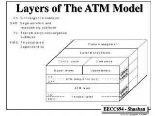
1.5.2 Layered Artecture in ATM Networks 1. User plane : 사용자 정보를 실제 전송하는 기능과 이와 관련된 흐름제어, 에러복구 2. Control plane : call과 connection의 제어 를 담당. call이 발생하면 call정보를 SAAL (Signalling AAL)을 거쳐 제어셀을 만들어 전달 3. Management plane : 계층관리+평면관리 4. Layer management : 각 계층의 자원(resource) 과 parameter 그리고 OAM(Operation and Mainte- Nance) 정보의 흐름을 관리 5. Plane management : 모든 평면들사이의 역할 들을 조정한다. B-ISDN ATM Protocol Reference Model
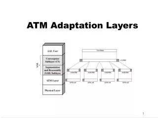
1.5.2.2 ATM Adaptation Layer(AAL Layer) (1) • 특성이 다른 개별서비스마다 유사한 서비스는 적응기능을 공유 [표 1.2 AAL service class] • AAL은 사용자에게 network 전송을 가능하게 해주며 에러 검출과 digital clock recovery를 통해 network QoS(Quality of Service)를 제공한다.
1.5.2.2 ATM Adaptation Layer(AAL Layer) (2) • AAL2 for class 2 service (ITU-T) 1. Transfer of the variable bit rate information service data units i.e. packetization in cells. 2. Transfer of the timing relation between source and destination. 3. Indication of the lost or errored information whice is not recovered by the AAL
1.5.2.2 ATM Adaptation Layer(AAL Layer) (3) • 사용자 QoS를 제공하기 위한 AAL의 기능 1. Sementing and reassembling the user information. 2. Handling the information vairations in cell transmission delay. 3. Handling the lost and misdelivered cells. 4. Recovering the source clock at the receiver. 5. Monitoring the user information field for bit errors and possible corrective action.
1.5.2.2 ATM Adaptation Layer(AAL Layer) (4) • AAL Layer의 부계층(sublayer) 1. Segmentation and Reassembly(SAR) sublayer • - sequence number(SN) field (4bits) : • - Cell Type(CT) field (4bits) : cell의 내용물이 무엇인지를 알려준다. • - length identifier(LI) field (6bits) : 실제적인 payload의 길이가 얼마 • 인지를 나타낸다. • - Forward Error Correction(FEC) (10bits) : 2개의 correlated errors를 • 고칠 수 있다.
1.5.2.2 ATM Adaptation Layer(AAL Layer) (5) • AAL Layer의 부계층(sublayer) 2. Convergence Sublayer(CS) - CS-PDU내에 time-stamps(real time synchronization word)를 삽입 함으로써, 가변비트의 오디오와 비디오 서비스의 clock recovery - sequence number processing(lost and misdelivered cells을 탐지) - SAR-PDU의 FEC와 SN field를 사용하여 오디오와 비디오 서비스를 위한 Forward Error Correction(FEC)를 수행
1.5.2.3 Lower ATM Network Layers(1) • ATM, Physical Layer의 2계층이 존재 1. ATM Layer : OSI network layer에 해당. 다음과 같은 기능을 수행 (1) Network management (2) Cell multiplexing and demultiplexing (3) Priority access management (4) Cell header generation and extraction (5) Appending and checking head error control (6) Cell rate decoupling by suppression and insertion of idel cells. - statistical multiplexing으로 인해, cell 손실발생과 전송 딜레이의 관점에서 network QoS를 제공할 수 있다(maximum value and jitter).
1.5.2.3 Lower ATM Network Layers(2) 1. Physical Layer : 비트레벨에서 정보의 코딩을 담당. 2개의 부계층으로 나누어짐. (1) Transmission convergence sublayer : cells을 비트 스트림(stream)으로 바꾸어준다. cell delineation, header error check and correction, scramble and unscramble (2) Physical medium sublayer : 전송매체의 종류에 따른 변조 방식을 결정 즉, 비트 타이밍과 동기화의 기능을 제공
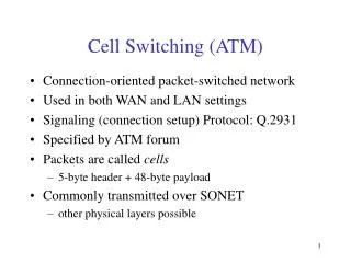
1.6 Cell Structure 1.Fixed and Variable Length Cells : switching performances 와 transmission bandwidth efficiency가 주요 요소 (1)switching performance : switching speed와 hardware complexity을 고려 (2)Transmission bandwidth efficiency=
Transmission efficiency 결론)가변길이 cell 을 사용할 때 transmission efficiency의 gain은 고정길이 cell을 사용하는 것 보다 더 나쁘다. 가변길이 cell이 전송하는데 있어 복잡한 방법을 요구하기 때문이다.
1.6 Cell Structure 2.Cell size : 세가지 파라미터들을 고려해야 한다. (1)전송비율 : cell size와 함께 증가한다. (2)Delay : voice를 적용하기 위해 24ms로 제한다. (3)Implementation complexity : Cell speed와 cell size의 tradeoff을 적용. 결론)적당한 cell 길이는 32 byte~ 64byte
1.6 Cell Structure 3. Cell structure : header field 5 byte + information field 48 bytes -Header Field (1)GFC(Generic Flow Control) (2)VPI(Virtual Channel Identifier) (3)PT(Payload Type) (4)CLP(Cell Loss Priority) (5)HEC(Head Error Control)