Download
1 / 42
440 likes | 742 Views
OSI LAYERS-Networks. Tony Caleb D 14-July-2010. OSI: Open System Interconnection . Developed by the International Organization for Standardization in 1974. There are seven layers in OSI reference Model . It is a layered approach. OSI Reference Model. An Exchange using the OSI Layers.

E N D
OSI LAYERS-Networks Tony Caleb D 14-July-2010
OSI: Open System Interconnection . Developed by the International Organization for Standardization in 1974. There are seven layers in OSI reference Model . It is a layered approach. OSI Reference Model
Layer - 7 Upper Layer or Software Layer Lower Layer or Hardware Layer Layer - 6 Layer - 5 Heart of OSI Layer - 4 Layer - 3 Layer - 2 Layer - 1 OSI Reference Model Application Presentation Session Transport Network Data Link Physical
Application Presentation Session Transport Network Data Link Physical Application Layer Application Layer is responsible for providing Networking Services to the user. It is also known as Desktop Layer. Identification of Services is done using Port Numbers. Ports are Entry and Exit Points to the Layer Total No. Ports 0 – 65535 Reserved Ports 0 – 1023 Open Client Ports 1024 – 65535 Application
Client Client Web Server Web Server Example of HTTP request http://www.zoomgroup.com
Client Web Server Example of HTTP request HTTP Request http:// www.zoomgroup.com Webpage HTTP Request Listen on Port 80 Sending HTTP Reply Webpage Received HTTP Reply http://www.symantec.com Webpage
Examples of Networking Services Service Port No. HTTP 80 FTP 21 SMTP 25 TELNET 23 TFTP 69
Presentation 80 21 25 53 67 69 Session Transport Network Data Link Physical Data flow from Application Layer Application Data
Application Presentation Session Transport Network Data Link Physical Presentation Layer Presentation Layeris responsible for converting data into standard format. Examples : JPEG, MPEG, MIDI, WAV, MP3 Following tasks are perform at Presentation layer : Encoding – Decoding Encryption – Decryption Compression – Decompression Presentation
Application Presentation Session Transport Network Data Link Physical Data flow from Presentation Layer Data Data
Application Presentation Session Transport Network Data Link Physical Session Layer Session Layer is responsible for establishing, maintaining and terminating session. Session ID works at Session Layer. Examples : RPC Remote Procedure Call SQL Structured Query Language NFS Network File System Session
Application Presentation Session Transport Network Data Link Physical Data flow from Session Layer Data Data Data
Application Presentation Session Transport Network Data Link Physical Transport Layer • Transport Layer is responsible for end-to-end connectivity. It is also known as the heart of OSI Layers. Following tasks are performed at the Transport Layer : - • Identifying Service • Multiplexing & De-multiplexing • Segmentation • Sequencing & Reassembling • Error Correction • Flow Control Transport
TCP UDP • Transmission Control Protocol • Connection Oriented • Acknowledgement • Reliable • Slower • Port No. 6 • e.g. HTTP, FTP, SMTP • User Datagram Protocol • Connection Less • No Acknowledgement • Unreliable • Faster • Port No. 17 • e.g. DNS, DHCP, TFTP Identifying Service
Application Presentation Session 80 21 25 53 67 69 Network Data Link TCP - 6 UDP - 17 Physical Multiplexing & De-multiplexing Transport
A B Segmentation Hello! How are you ? Hello! How are you ? Hello! How Are You ?
you Hello! How ? are A B Sequencing & Reassembling Hello! How are you ? Hello! How are you ? You Hello! How ? Are You Hello! How ? Are Hello! Are You ? How
Hello! How are you ? A B Sequencing & Reassembling Hello! How are you ? Hello! How are you ? Hello! How are you ? Hello! 1/5 Hello! 1/5 Are 3/5 Are 3/5 You 4/5 You 4/5 ? 5/5 ? 5/5 How 2/5 How 2/5 You 4/5 Hello! 1/5 How 2/5 ? 5/5 Are 3/5
Hello! 1/5 Are 3/5 You 4/5 ? 5/5 Hello! How are you ? A B ErrorCorrection Segment Missing Hello! How are you ? Hello! How are you ? Hello! How are you ? Hello! 1/5 Hello! 1/5 Are 3/5 Are 3/5 You 4/5 You 4/5 ? 5/5 ? 5/5 How 2/5 How 2/5 You 4/5 Hello! 1/5 ? 5/5 Are 3/5 How 2/5
A B Flow Control - Windowing Sending 3-window Received 3-window PC-A can send 4 Segments at a time to PC-B Ack. Received-4 Ack-Rec-3 Sending 5-window Received 4-window
Application Presentation Session Transport TH Network Data Link Physical Data flow from Transport Layer Data Data Data Segment Data
Application Presentation Session Transport Network Data Link Physical Network Layer • Network Layer is responsible for providing best path for data to reach the destination. Logical Addressing works on this layer. Router is a Network Layer device. • It is divided into two parts • Routed Protocols • e.g. IP, IPX, Apple Talk. • Routing Protocols • e.g. RIP, IGRP, OSPF, EIGRP Network
Segment Hello! How are you ? Segment A B 192.168.1.1 192.168.1.2 Routed Protocols Segment Hello! How are you ? Source IP 192.168.1.1 Destination IP 192.168.1.2 Source IP 192.168.1.1 Destination IP 192.168.1.2
A Routing Protocols www.symantec.com
Application Presentation Session Transport e.g. Router Network NH Data Link Physical Data flow from Network Layer Data Data Data Segment Packet Segment
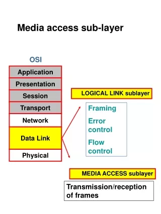
Application Presentation Session Transport Network Data Link Physical Data link Layer • Datalink Layer is divided into two Sub • LLC – Logical Link Control • It talks about Wan protocols e.g. PPP, HDLC, Frame-relay • MAC – Media Access Control • It talks about Physical Address. It is a 48 bit address i.e. 12 digit Hexadecimal Number. • It is also responsible for Error Detection • Devices working on Data Link Layer are Switch, Bridge, NIC. Data Link
Packet A B 192.168.1.1 00-20-18-C0-07-71 192.168.1.2 00-20-18-C0-07-72 Error Detection – CRC Check PC-A CRC No. 33333 PC-B CRC No. 11114 Error Detected For Error Correction Contact Source Transport layer Packet Hello! How are you ? 00000 11114 46323 99434 89696 99323 55434 00000 43434 32434 43434 32434 55434 99323 22222 99434 46323 11114 Error Detected Source MAC 00-20-18-C0-07-71 Destination MAC 00-20-18-C0-07-72 22222 89696 33333
Packet Hello! How are you ? Packet A B 192.168.1.1 00-20-18-C0-07-71 192.168.1.2 00-20-18-C0-07-72 Error Detection – CRC Check Packet 22222 22222 00000 20202 99323 46323 99434 43434 89696 11114 99323 46323 43434 99434 55434 11114 20202 Source MAC 00-20-18-C0-07-71 Destination MAC 00-20-18-C0-07-72 32434 00000 Source MAC 00-20-18-C0-07-71 Destination MAC 00-20-18-C0-07-72 55434 89696 32434
Application Presentation Session Transport Network e.g. Switch Data Link DH DT Physical Data flow from Data Link Layer Data Data Data Segment Packet Frame Packet Packet
Application Presentation Session Transport Network Data Link Physical Physical Layer Physical Layer is responsible for electrical, mechanical and procedural checks. Data will be converted into Binary (i.e) 0’s & 1’s. Data will be in the form of electrical pulses if it is Coaxial or Twisted Pair cable and in the form of Light if it is Fiber Optic Cable. Devices working at Physical Layer are Hubs, Repeaters, Cables, Modems etc. Physical
Frame Hello! How are you ? Frame A B Physical Layer Example Frame 1010101010101010 1010101010101010 1010101101010101010101010 0101011010101010101010101 1010101101010101010101010 0101011010101010101010101 0101011010101010101010101
Application Presentation Session Transport Network Data Link e.g. Hub Physical Data flow from Physical Layer Data Data Data Segment Packet Frame Bits
A B Application Application Presentation Presentation Session Session Transport Transport TH TH TH Data Network Network Segment NH NH NH Data Link Data Link Packet DH Packet DH DH DT DT DT Physical Physical Data Encapsulation & De-capsulation Data Data Data Data Data Data Segment Segment Data Packet Packet Segment Frame Frame Packet Packet Bits Bits
Application Presentation Session Transport Network Data Link Physical Comparing OSI with TCP/IP Layers OSI Layers TCP/IP Layers Application Transport Internet Network Access