Download
1 / 34
350 likes | 518 Views
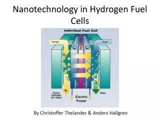
NTB INTERSTAATLICHE HOCHSCHULE FÜR TECHNIK BUCHS. NMW. KTI Review Meeting, December 16, 2005. Workpackage 1: Fuel Cell Development. U. P. Muecke (NMW) and S. Rey-Mermet (EPFL). WP 1: Year 1 Milestones. performance 200 mW/cm 2 @ 550°C external electrical connections. Fuel Cell.

E N D
NTB INTERSTAATLICHE HOCHSCHULE FÜR TECHNIK BUCHS NMW KTI Review Meeting, December 16, 2005 Workpackage 1: Fuel Cell Development U. P. Muecke (NMW) and S. Rey-Mermet (EPFL)
WP 1: Year 1 Milestones • performance 200 mW/cm2 @ 550°C • external electrical connections Fuel Cell • butane conversion rate > 90% • post-combustor with gas oxidation > 98% Gas Processing • thermal insulation concept with • Tinside 550°C, Toutside 50°C, <10 cm3 • structures for validation critical points • thermal system demonstrator with • simulated 2 W heat source Thermal System Project Management • battery expert • industrial partner
Main Achievements after 6 Months First cell working at 12 mW / cm2
WP 1: Overview and Structure NTB INTERSTAATLICHE HOCHSCHULE FÜR TECHNIK BUCHS Electrolyte Ce0.8Gd0.2O1.9 NMW Anode Ni-Ce0.8Gd0.2O1.9 Anode Ni-Ce0.8Gd0.2O1.9 Cathode La0.6Sr0.4Co0.2Fe0.8O3 Cathode La0.7Sr0.3CoO3 Sputtering Spray pyrolysis Pulsed laser deposition Electrolyte Ce0.8Gd0.2O1.9, Y0.08Zr0.92O2-x Cathode Electrolyte Anode Substrate & Design Glas Ceramic Substrate & Design Silicon & Ni grid
WP 1 Overview • WP 1.1 Electrolyte • fabrication, electrical conductivity • WP 1.2 Ni/CGO anode thin film • morphology, electrical conductivity, electrochemical characterization • WP 1.3 LSCF cathode • morphology, electrical conductivity, electrochemical characterization • WP 1.4 Microfabrication and contacting • WP 1.5 PEN Integration and testing
WP 1.1 Electrolyte Fabrication 200 nm 200 nm Pulsed laser deposition (PLD) Spray pyrolysis (SP) 200 nm • dense and crack-free electrolyte films • thickness 100-500 nm 200 nm (sputtered Pt) Ce0.8Gd0.2O1.9-x Ce0.8Gd0.2O1.9-x Substrate in all cases sapphire. sapphire
WP 1.1 Electrolyte Properties Thermal stability Electrical conductivity • ionic conductivity ~ 1 S/m at 700° C in air • predominant ionic conductor for T < 600° C Ce0.8Gd0.2O1.9-x Ce0.8Gd0.2O1.9-x • high thermal stability for T < 1100° C no grain coarsening no long term degradation
WP 1.1 Alternative Electrolyte - YSZ 1 µm Spray pyrolysis processing Electrical conductivity Y0.08Zr0.92O2-x Y0.08Zr0.92O2-x 1.18 eV • dense and crack-free electrolyte film • ionic conductivity ~ 0.75 S/m at 700° C in air
WP 1.2 Electrolyte Conclusions • Crack-free and dense CGO (SP and PLD) and YSZ (SP) films • Ionic conductivity surpasses milestone • Good thermal stability
WP 1.2 Morphology of Ni/CGO Anode 200 nm 200 nm 200 nm • crack-free • > 30% porosity • 100-1000 nm thickness possible conventional Ni-YSZ cermet EPFL sputtering (top and cross) 200 nm ETH spray pyrolysis (top and cross)
Conductivity of 60/40 Ni-CGO anode metallic conductivity milestone 100 S/cm 550 S/cm @ 600°C literature: 400-800 S/cm degradation: 0.85%/1000 hours Yin et al. 2004 Pratihar et al. 2005
Electrochemical Characterization - Intro Half Cell (A vs. R) Up Total Cell (A vs. C) I U Ni-CGO anode film Electrochemical Impedance Spectroscopy (EIS) Rp polarization resistance
Rp as a function of fuel gas H2O content H2O Water vapor in the fuel decreases Rp in low frequency part
Rp as a function of polarization Up i I U Anodic overpotential => production of water Up same effect as adding H2O to fuel => Rp decreases
Rp - comparison water/polarization applying overpotential Up water in anode gas PH2 / PH2O PO2 diffusion accounts for changes equivalent circuit fitting R2 R3
WP 1.2 Anode - Conclusions • 0.1-1 μm thick crack-free films with >30% porosity • Conductivity surpasses milestone by factor 5 • Conductivity stable over 1500 hours at 550°C • Good electrochemical performance in dry and humidified gas Next: • Improved low temperature sintering
WP 1.3 Cathode Microstructure & Conductivity A C Good electrical conductivity. Porosity > 20 % is achieved by spray pyrolysis.
WP 1.3 Cathode Phase 2 Theta / deg La0.3Sr0.7CoO3 EPFL La0.6Sr0.4Co0.2Fe0.8O3 ETH Desired perovskite phase is obtained. G.C. Kostogloudis, C. Ftikos, Solid State Ionics, 1999, 126 (1-2), 143. J. ten Elshof, J. Boeijsma, Powder Diffr, 1996, 11 (3), 240.
WP 1.3 Cathode Performance Rp / Wcm2 J.A. Lane, P.H. Middleton, H. Fox, B.C.H. Steele, J.A. Kilner, In 2nd International Symposium on Ionic and Mixed Conducting Ceramics. 1994 J.M. Ralph, A.C. Schoeler, M. Krumpelt, J. Mater. Sci., 2001, 36 (5), 1161.
WP 1.3 Cathode Conclusions • Crack-free films with >20% porosity achieved • Good electrical conductivity • Excellent electrochemical performance Next: • Exploring new materials, e.g. Ba0.5Sr0.5Co0.8Fe0.2O3
WP 1.4 Microfabrication and Contacting Pt foturan glass foturan glass 25 mm foturan irradiated electrolyte anode cathode free-standing membrane etching contacted m-SOFC
WP 1.5 PEN Integration and Testing Fuel E I Air Gas mixing unit Fuel Cell Water Test rig with computer controlled gas supply and data acquisition Inert Oxygen Exhaust
WP 1.5 Measured Cell Performance LSCF (SP) YSZ PLD Ni-CGO (SP) Power density ~12 mW / cm2 OCV 170 mV T ~ 550°C
WP 1.5 Projected Cell Performance today Projected cell performance based on results obtained for single layers
Actual design fabrication Contact anode Contact cathode Current collector 2.4 cm Membrane Ni grid
Electrolyte membrane Ce0.8Gd0.2O2 (CGO) • Dense, polycrystalline film • Ionic conductivity as in bulk ceramics • Better than project specs
Stress control of CGO-film Oxygen uptake 100 % Ar, 15 mT, RT • Stress controlled by annealing in oxygen • Freestanding membranes can be fabricated (2 mm) • Thermal stability with 150 nm: up to 300 °C
Nickel Gridfor membrane reinforcement and current collection 2. Current collector anode 4. CGO 9. Ni grid 100 mm
Free standing CGO membranes with nickel grid 50 mm Annealing for low stress 100 mm No annealing
Summary Achievements 12 mW / cm2 s > 0.5 S / cm Membrane Stable up to 500°C Anode Cathode s > 550 S / cm Rp < 1 Wcm2 s > 100 S / cm Rp < 1 Wcm2
Validation of Milestones and Deliverables • WP 1.1: Electrolyte Month 3: - dense and crack-free electrolyte with composition CGO 80/20 (NMW, EPFL) - conductivity @ 500°C-800°C in air characterized; s > 0.2 S/m @ 700°C in air (NMW, EPFL) - microstructure characterized (NMW, EPFL) Month 6: - electrical characterization of free standing membrane (NMW, EPFL) - stress measurements as input for PEN design optimization (EPFL) - YSZ electrolytes characterized (NMW) ongoing • Deliverables: • Month 6: - selected samples NMW EPFL for stress measurements: dimensions: 4`` or 1 cm x 3 cm, substrate: Si or Foturan • WP 1.2: Anode • Month 3: - crack-free Ni-CGO films, s > 100 S/cm @ 600C, > 30% porosity in reduced state (NMW, EPFL) • Month 6: - electrochemical characterization of NMW and EPFL films (NMW) • - thermal stability and degradation f(T, t) (NMW, EPFL) • - stress measurements (EPFL) • Deliverables: • Month 3: - selected samples from EPFL NMW for electrochemical characterization: dimensions to be specified by U. Mücke • - substrate: YSZ polished bulk pellet (from NMW) • Month 6: - selected samples from NMW EPFL for stress measurements: dimensions: 4`` or 1 cm x 3 cm, substrate: Si or Foturan ongoing
Validation of Milestones and Deliverables • WP 1.3: Cathode • Month 3: - crack-free LSCF films, s > 100 S/cm @ 600C, > 20% porosity (NMW, EPFL) • Month 6: - electrochemical characterization of NMW and EPFL films (NMW) • - stress measurements (EPFL) • Deliverables: • Month 3: - selected samples from EPFL NMW for electrochemical characterization: dimensions to be specified by D. Beckel • - substrate: CGO polished bulk pellet (from NMW) • Month 6: - selected samples from NMW EPFL for stress measurements: dimensions: 4`` or 1 cm x 3 cm, substrate: Si or Foturan ongoing • WP 1.4 Microfabrication and Electrical Contacting • Month 3: - design of standard PEN and of electrical contacts available (NTB, NMW, EPFL) • - first microstructured PEN elements ready for testing (NTB, NMW, EPFL) • - proof of concept for Ni grid (EPFL) • Month 6: - re-design of PEN element and electrical contacting (NTB, NMW, EPFL) • - Integration of Ni grid in process flow (EPFL) • Deliverables: • Month 3: - first microstructured PEN element NTB, EPFL NMW for testing: dimensions to be specified by U. Mücke • Month 6-12: - continuous supply of thin films and PEN elements for testing: NTB, NMW, EPFL
Validation of Milestones and Deliverables • WP 1.5: PEN Integration and Testing • Month 3: - test rig for PEN characterization operating (NMW) • Month 6: - first electochemical testing results of integrated PENs (NMW, EPFL, NTB)
Questions ? First cell working at 12 mW / cm2