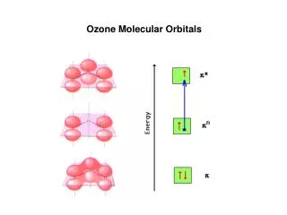
Molecular Orbitals
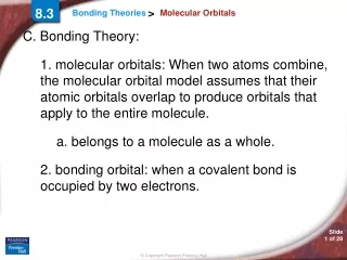
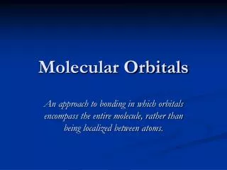
Molecular Orbitals. An approach to bonding in which orbitals encompass the entire molecule, rather than being localized between atoms. Molecular Orbitals. Molecular orbitals result from the combination of atomic orbitals.

Molecular Orbitals
E N D
Presentation Transcript
Molecular Orbitals An approach to bonding in which orbitals encompass the entire molecule, rather than being localized between atoms.
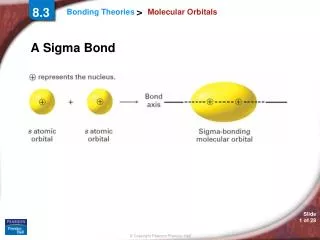
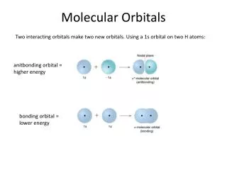
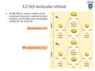
Molecular Orbitals Molecular orbitals result from the combination of atomic orbitals. Since orbitals are wave functions, they can combine either constructively (forming a bonding molecular orbital), or destructively (forming an antibonding molecular orbital).
Molecular Orbitals Molecular orbitals form when atomic orbitals with similar energies and proper symmetry can overlap. Atomic orbitals with differing energies or the wrong spatial orientation (orthogonal) do not combine, and are called non-bonding orbitals.
Need for MO Theory Valence bond theory fails to explain the bonding in many simple molecules. The oxygen molecule has a bond length and strength consistent with a double bond, and it contains two unpaired electrons.
Need for MO Theory Valence bond theory predicts the double bond, but not the paramagnetism of oxygen. O=O : : : :
Need for MO Theory Resonance is another example of the limitations of valence bond theory. Bond lengths and strengths are intermediate between single, double or triple bonds. Molecular orbital theory is often a better approach to use with molecules that have extended π systems.
Molecular Orbital Theory In order to simplify things, we’ll consider the interaction of the orbitals containing valence electrons to create molecular orbitals. The wave functions of hydrogen atom A and hydrogen atom B can interact either constructively or destructively.
Molecular Orbital Theory Constructively: Ψ(σ) or Ψ+ = (1/√2 ) [φ(1sa) + φ(1sb) ] Destructively: Ψ(σ*) or Ψ- = (1/√2 ) [φ(1sa) - φ(1sb) ]
Molecular Orbital Theory The bonding orbital results in increased electron density between the two nuclei, and is of lower energy than the two separate atomic orbitals.
Molecular Orbital Theory The antibonding orbital results in a node between the two nuclei, and is of greater energy than the two separate atomic orbitals.
Molecular Orbital Theory The result is an energy level diagram with the bonding orbital occupied by a pair of electrons. The filling of the lower molecular orbital indicates that the molecule is stable compared to the two individual atoms.
Molecular Orbital Theory The bonding orbital is sometimes given the notation σg, where the g stands for gerade, or symmetric with respect to a center of inversion. + - + The signs on the molecular orbitals indicate the sign of the wave function, not ionic charge.
Molecular Orbital Theory The anti-bonding orbital is sometimes given the notation σu, where the u stands for ungerade, or asymmetric with respect to a center of inversion. + - + The signs on the molecular orbitals indicate the sign of the wave function, not ionic charge.
Rules for Combining Atomic Orbitals • The number of molecular orbitals = the number of atomic orbitals combined. • The strength of the bond depends upon the degree of orbital overlap.
Experimental Evidence Photoelectron spectroscopy (PES) is a technique in which a beam of ultraviolet light with an energy of 21 eV is used to irradiate molecules. The energy is high enough to eject electrons. The kinetic energy of the emitted electrons is measured, and used to determine the energy level of the electron.
Experimental Evidence The technique allows for the measurement of specific ionization energies (I). Each ionization energy represents the removal of an electron from a specific molecular orbital.
Experimental Evidence Electrons in lower energy levels require more energy to be removed, and are ejected with less kinetic energy. hνo = I + Ekinetic
Period 2 Diatomic Molecules For the second period, assume that, due to a better energy match, s orbitals combine with s orbitals, and p orbitals combine with p orbitals. The symmetry of p orbitals permits end-on-end overlap along the bond axis, or side-by-side overlap around, but not along, the internuclear axis.
MOs using p orbitals - - + + - + - With the x axis as the bond axis, the px orbitals may combine constructively or destructively. The result is a σ bonding orbital and a σ anti-bonding orbital.
MOs using p orbitals - - + + - + - The designation σ indicates symmetric electron density around the internuclear (x) axis. The + and – signs indicate the sign of the wave function, and not electrical charges.
MOs using p orbitals - - + + - + - Some texts will use the symmetry designations of g (gerade) or u (ungerade) instead of indicating bonding or anti-bonding.
MOs using p orbitals - - + + σg - + - For these orbitals, the bonding orbital is gerade, or symmetric around the bond axis.
MOs using p orbitals σu - - + + σg - + - For these orbitals, the anti-bonding orbital is asymmetric about the bond axis, and is designated as σu. Note that the designations of u or gdo not correlate with bonding or anti-bonding.
π Molecular Orbitals + - - + + - side-by-side overlap The orbital overlap side-by-side is less than that of overlap along the bond axis (end-on-end). As a result, the bonding orbital will be higher in energy than the previous example.
π Molecular Orbitals + - - + + - side-by-side overlap π orbitals are asymmetric with respect to the bond axis. There is electron density surrounding the bond axis, with a node along the internuclear axis.
π Molecular Orbitals + - - + + πu - side-by-side overlap Some texts use the subscripts g and u instead of bonding and anti-bonding. In this example, the bonding orbital is ungerade, or asymmetric about a center of symmetry.
π Molecular Orbitals + - πg - + + πu - side-by-side overlap The anti-bonding orbital is gerade, or symmetric about a center of symmetry.
Molecular Orbital Diagram This is a molecular orbital energy level diagram for the p orbitals. Note that the σ bonding orbital is lowest in energy due to the greater overlap end-on-end. σu πg 2p 2p πu σg
Molecular Orbital Diagram The alternate notation is provided on the right side of the energy level diagram. σu πg 2p 2p πu σg
Molecular Orbital Diagrams • Electrons preferentially occupy molecular orbitals that are lower in energy. • Molecular orbitals may be empty, or contain one or two electrons. • If two electrons occupy the same molecular orbital, they must be spin paired. • When occupying degenerate molecular orbitals, electrons occupy separate orbitals with parallel spins before pairing.
Molecular Orbital Diagrams Although molecular orbitals form from inner (core) electrons as well as valence electrons, many molecular orbital diagrams include only the valence level.
Molecular Orbital Diagrams For O2, there will be a total of 12 valence electrons that must be placed in the diagram.
Molecular Orbital Diagrams For O2, there will be a total of 12 valence electrons that must be placed in the diagram.
Molecular Orbital Diagrams For O2, there will be a total of 12 valence electrons that must be placed in the diagram. 2p 2p 2s 2s
MO Diagram for O2 σ*u The molecular orbital diagram for oxygen shows two unpaired electrons, consistent with experimental data. π*g 2p 2p πu σg σ*u 2s 2s σg
Bond Order Bond order is an indicator of the bond strength and length. A bond order of 1 is equivalent to a single bond. Fractional bond orders are possible. The bond order of the molecule = (# e- in bonding orbtls)- (# e- in anti-bonding orbtls) 2 2
MO Diagram for O2 The bond order of O2 is: 8-4 = 2 2 This is consistent with a double bond. σ*u π*g 2p 2p πu σg σ*u 2s 2s σg
MO Diagram for O2 This energy level diagram works well for atoms in which the 2s and 2p levels are fairly far apart. These are the elements at the right of the table: O, F and Ne. σ*u π*g 2p 2p πu σg σ*u 2s 2s σg
Experimental Evidence Oxygen is paramagnetic, consistent with having two unpaired electrons. In addition, photoelectron spectroscopy (PES) can be used for determining orbital energies in molecules. The molecule is bombarded with UV or X-rays to remove an electron from the molecule. The kinetic energy of the emitted electron is measured and subtracted from the incident radiation to determine the binding energy of the electron.
Photoelectron Spectroscopy The result is a spectrum of absorptions which are correlated to the molecular orbitals of the molecule. In addition, electrons ejected from bonding orbitals show more vibrational energy levels than electrons emitted from anti-bonding or non-bonding orbitals.
MO diagram for Li through N The elements on the left side of period 2 have a fairly small energy gap between the 2s and 2p orbitals. As a result, interaction between s and p orbitals is possible. This can be viewed in different ways.
MO diagram for Li through N In some approaches, the s orbital on one atom interacts with the p orbital on another. The interaction can be constructive or destructive.
MO diagram for Li through N In another approach, the s and p orbitals on the same atom interact in what is called orbital mixing. Either approach yields the same result. The σ bonding and anti-bonding orbitals are raised in energy due to the interaction with a p orbital.
MO diagram for Li through N σ*u π*g σg πu σ*u σg
σ*u π*g σg πu σ*u σg MO diagram for N2 N2 has 10 valence electrons.
Experimental Evidence The photoelectronic spectrum of nitrogen is consistent with a molecular orbital approach. Electrons emitted from bonding orbitals show vibrational excitations. σg πu σ*u
σ*u π*g σg σg πu πu σ*u σ*u σg Experimental Evidence
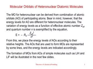
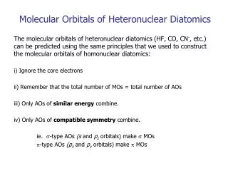
Heteronuclear Diatomic Molecules The more electronegative atom will have orbitals of lower energy, and therefore contribute more to the bonding orbitals. The less electronegative atom has orbitals of higher energy, and contributes more to the anti-bonding orbitals.
Rules for Combining Atomic Orbitals For heteronuclear molecules: 1. The bonding orbital(s) will reside predominantly on the atom of lower orbital energy (the more electronegative atom). 2. The anti-bonding orbital(s) will reside predominantly on the atom with greater orbital energy (the less electronegative atom).