Advanced Wind Tunnel Techniques for Structural Response Simulation
230 likes | 488 Views
Explore various wind tunnel techniques, from simulating atmospheric boundary layers to modeling thunderstorm downbursts, for accurate testing and modeling of structural responses. Learn about dimensional analysis, measurement of local pressures, and frequency response systems. Discover how aeroelastic models aid in understanding overall loads on tall buildings.

Advanced Wind Tunnel Techniques for Structural Response Simulation
E N D
Presentation Transcript
Wind-tunnel techniques Wind loading and structural response
Model mounted on 3-wheel carriage Contraction Air jet Fly wheel Gas engine Propeller Wind-tunnel techniques • Original wind tunnel of W.C. Kernot - 1893
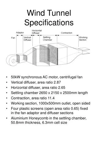
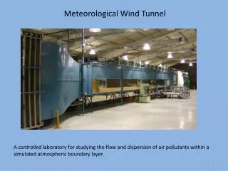
Flow Fan Straightener Test Section FLOW Diffuser Contraction Screen Wind-tunnel techniques • Two types : open circuit and closed circuit Open circuit type (fan downstream of test section) : Blowing type - fan upstream of test section : test section nearly at atmospheric pressure
10-15 m Wind-tunnel techniques • Simulation of atmospheric boundary layer : Natural growth method : Boundary layer is grown naturally over surface roughness elements Boundary layer thickness is usually too small to model complete atmospheric boundary layer - use auxiliary ‘tripping’ devices
Counihan method Roughness Fins hT Castellated barrier ~4hT Wind-tunnel techniques • Simulation of atmospheric boundary layer : Methods for short test sections : Other devices : triangular ‘spires’ , graded grids
Barrier hB >30hB Wind-tunnel techniques • Simulation of ‘surface layer’ (<100 m) : Barrier - roughness : Eddy size ( integral length scale) larger than other methods Useful for model scales of 1/50 to 1/200 (e.g. low-rise buildings)
Wind-tunnel techniques • Simulation of hurricane boundary layers : Near eye wall : steep profile up to about 100 metres - then nearly constant Turbulence is higher in hurricanes (but ‘patchy’) Can use non-hurricane boundary layer for rougher terrain in wind tunnel simulations
Vertical board Blower Working section Contraction Diffusing section Jet Wind-tunnel techniques • Simulation of thunderstorm downburst by impinging jet : Stationary downbursts only are modelled - continuous not transient
Wind-tunnel techniques • Modelling rules - dimensional analysis : Non-dimensional response/pressure coefficients = f(1, 2, 3etc…) ’s are non-dimensional groups associated with flow and structure ’s should be matched in full scale and model scale Examples of ’s : Iu, Iv, Iw - turbulence intensities Uh/ - Reynolds Number ( is kinematic viscosity) E/aU2 - Cauchy Number (elastic forces in structure/inertial forces in flow) s /a - density ratio (density of structure / air density)
Wind-tunnel techniques • Modelling rules - dimensional analysis : Non-dimensional numbers may not be independent For example, reduced frequency : i.e. proportional to square root of the Cauchy Number divided by the density ratio
Wind-tunnel techniques • Modelling rules - dimensional analysis : Not possible to obtain equality of all non-dimensional groups Scaling requirements might be relaxed Judgement based on experience and understanding of mechanics of the phenomena Quality assurance manuals and standards for wind-tunnel testing are now available - e.g. A.W.E.S. , A.S.C.E.
Wind-tunnel techniques • Measurement of local pressures : Fluctuating and short duration peak pressures must be measured Local pressures - measurement done with single measurement ‘tap’ Area-averaged pressures with multiple pressure taps manifolded together Multiple input tubes - single output tube to electronic pressure sensor
Overestimation depends on correlation between point pressures on the area 1.8 1.6 1.4 1.0 0.8 0.6 0.4 0 Assumed correlation function = exp (-Cr) B Rd Rc Rd discrete averaging Rc continuous averaging 0 2 4 6 8 10 CB B 2 Wind-tunnel techniques • Area-averaged pressures : Discrete averaging overestimates continuous average fluctuating loads Variance of averaged panel force to variance of point pressure
System within +/- 15% limits to 150 Hertz Wind-tunnel techniques • Frequency response of measurement system : Require amplitude response ratio equal to 1.0 ( +/- small error) over a defined frequency range
350 300 250 Phase lag (degrees) 200 150 100 50 0 0 100 200 300 400 Frequency (Hertz) Wind-tunnel techniques • Frequency response of measurement system : Require phase response to vary linearly over a defined frequency range Time delay = (1/n) (phase angle / 2) For constant time delay, phase angle should be proportional to frequency, n
Transducer volume (a) Short tube Restrictor (b) Restricted tube Controlled leak (c) Leaked tube Wind-tunnel techniques • Types of tubing systems : Short tube : high resonant frequency but amplitude response rises fast Restricted tube : restrictor tube damps resonant peak Leaked tube : high pass filter, mean response is also reduced
h Gimbals Springs Strain gauges Electromagnet Aluminium disc Wind-tunnel techniques • Overall loads on tall buildings : Two techniques : aeroelastic models - resonant structural response is scaled motion of building in sway modes of vibration are reproduced - hence aeroelastic (e.g. aerodynamic damping) forces are included Base-pivotted aeroelastic model : Uses equivalence of rigid body rotation and movement of tall building in first mode with linear mode shape Model should be scaled to have the same density
h Six component strain gauge balance Wind-tunnel techniques • Overall loads on tall buildings : high-frequency base balance : mean and background aerodynamic forces only are measured model building supported on a stiff base balance to measure aerodynamic applied forces spectral densities of applied base bending moments are measured and used to compute resonant components in sway modes requires mode shape corrections, special processing for coupled modes, linked buildings
Spectral density U1 (>U2) U2 Simulated building frequency Modelfrequency in wind tunnel Usable frequency range for measurements Wind-tunnel techniques • High-frequency base balance : Frequency relationships : Support system should be made very stiff, and building model light to keep frequency above measurement range
Wind-tunnel techniques • Full aeroelastic models : Slender structures such as bridges and towers Elastic properties are concentrated in a ‘spine’ to which non-structural segments are attached to give correct aerodynamic shape and mass Length scale ratio and velocity scale ratio chosen to suit size and speed range of wind tunnel Frequency then obtained by equality of reduced velocity : Stiffness of spine obtained by requirement to keep frequency of structure equal in model and full scale
Segmented tower legs and deck Wind-tunnel techniques • Full aeroelastic models :