Download
1 / 30
300 likes | 476 Views
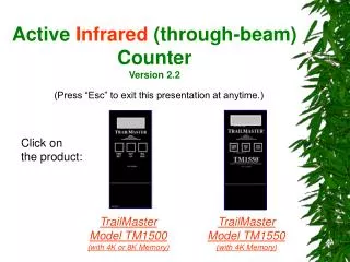
Active Infrared (through-beam) Counter Version 2.2. (Press “Esc” to exit this presentation at anytime.). Click on the product:. TrailMaster Model TM1500 (with 4K or 8K Memory). TrailMaster Model TM1550 (with 4K Memory). TrailMaster Model TM1500. Red alignment indicator light.

E N D
Active Infrared (through-beam) CounterVersion 2.2 (Press “Esc” to exit this presentation at anytime.) Click on the product: TrailMaster Model TM1500 (with 4K or 8K Memory) TrailMaster Model TM1550 (with 4K Memory)
TrailMaster Model TM1500 Red alignment indicator light Sight line for alignment with transmitter Power switch Camera Connector (for optional accessory) Power Switch Data Port (for optional data collector unit)
TM1500—Operation TrailMaster’s TM1500 is a two-piece active infrared trail monitoring system which sets up an invisible infrared beam across the trail between the transmitter and receiver. (90 ft./30 m. range) The infrared energy is transmitted as a wide beam from the transmitter, and received in a small 3/8" diameter window on the receiver. The only part of the transmitted beam which is sensitive to being broken is the narrow 3/8" beam which is received by the receiver. See Figure 1 below. By setting the beam at the chest height of the animal you wish to monitor, and controlling the length of time the beam must be blocked before it registers as an event, you can count only the animals you want, and ignore other animals or objects which pass through the beam. This patented system provides a monitor which is easy to align, but one with selective sensitivity to allow you to monitor an area for movement of specific game. The TM1500 active infrared trail monitor and its accessories are the standard by which all other trail monitors are measured. Active infrared technology has become the standard of the industry.
TM1500—Key Benefits Beam Type: Through-beam, active infrared. Maximum Recommended Range: 90 feet (distance between transmitter and receiver). Power: Four alkaline “C" batteries Transmitter. Four alkaline “C" batteries Receiver. Operates 30 to 90 days. Count Display: 4-digit internal LCD. Enclosure: Weather-proof; compact, rugged, and easy to set up with straps Dimensions: Receiver, 7.5 x 3.5 x 2.1 inches; Transmitter, 4.75 x 3.25 x 1.8 inches. Shipping Weight: Receiver, 1.6 lbs.; Transmitter, 1.0 lbs. (includes batteries). Operational features: The period counter can be left unattended is 30- to 90-days, in typical mild weather. Records date and time to the minute of each eventCan store over 1000 events. (Note, 4000 events for model 4K or 8,000 events for model 8K) Other features: Constant memory readout / 24 hr. clock; Low battery and alignment indicator lamp; external counter reset; external connector for remote accessories; auto shutoff of align mode; sight line for ease of alignment.
Important Note Before going to the field, refer to the operating manual for instructions on checking and setting the correct date and time for your location. Receiver face
TM1500—Installation Instructions Transmitter Unit Receiver Unit Click for more info
TM1500—Installation Instructions Recommended Tools: Screwdriver, (Philips head) Step 1. In forested locations, select a site along the trail with up to 10” diameter trees on both sides of the trail. The extra set(s) of straps (included in your order) can be used to lengthen the straps thus allowing the attachment to large diameter trees. Step 2. Mount the Receiver Unit (with nylon straps, provided on the unit) to one tree, with the sensor (located on the right side of the unit) facing the opposite tree. (Note, use the alignment sighting line to aim the receiver sensor in the direction of the opposite tree where the Transmitter unit will be mounted.)
TM1500—Installation Instructions Step 3. Turn “on” the Receiver unit’s power switch and press the “Set Up” button on the front of the unit. Step 4. Mount the Transmitter unit on the opposite tree (up to 90 feet away). Note, the sensor of the transmitter is located on the front face of the unit. This sensor should be aiming back towards the Receiver unit. Turn the power switch on.
TM1500—Installation Instructions Step 5. At this time, you should notice the “red” alignment indicator on the Receiver blinking to indicate when the transmitter and receiver units are aligned. Step 6. Tighten all mounting straps on each unit. Then, take several passes back and forth on the trail to verify that the counter is counting. If not, reposition the Receiver units to align the sensor’s beam.
TM1500—Calibration & Initial Setup . . .x After aligning the transmitter and receiver, you must clear (or reset to zero) the counter. To clear, you do the following . . . Receiver face
TM1500—Calibration & Initial Setup S. uP “Resetting the Counter” 1 Press here
TM1500—Calibration & Initial Setup c lr “Resetting the Counter” 2 Press here
TM1500—Calibration & Initial Setup 0 “Resetting the Counter” 3 Press here
TM1500—Calibration & Initial Setup 0 The counter is now ready to begin counting.
TM1500—Calibration & Initial Setup 0 Make a selection: REPEAT Demo CONTINUE
TM1500—Recording Collected Data To extract your collected date/time-stamped data from the counter, do the following...
TM1500—Recording Collected Data Note, the number displayed is the total counts (cumulative) for the entire sampling period.
TM1500—Recording Collected Data Note, the number displayed is the total counts (cumulative) for the entire sampling period. To find out when these counts occurred, do the following . . .
TM1500—Recording Collected Data …the date will appear (month.day) 12. 1 1 Press here
TM1500—Recording Collected Data …the time will appear (hour.minute) 15.31 2 Press here again
TM1500—Recording Collected Data …the count will appear 1 Note, the count displayed is a cumulative total of successive counts. 3 Press here again
TM1500—Recording Collected Data …when this message is displayed it indicates you have reached the end of the recorded counts. Ehru 4 Press here again
TM1500—Recording Collected Data …when this message is displayed it indicates you have reached the end of the recorded counts. Ehru 4 Press here again REPEAT Demo CONTINUE
TM1500—Recording Collected Data You should be recording this information onto the form. The form enclosed with your shipment may be different from the one shown here.
TM1500—Product Service Information Goodson and Associates, Inc. 10614 Widmer Lenexa, KS 66215 Contact: Bill Goodson Phone: 913-345-8555 or 1-800-544-5415 Fax: 913/345-8272 Website: www.trailmaster.com
End of Demonstration Return Home
TrailMaster Model TM1550 Basically, the TM1550 is a TM1500 with improved features. Greater range, non-volatile memory, passcode protection, and energy-conservation are just some of the advanced features.
The physical difference . . . Trail Master Model TM1550 Trail Master Model TM1500 Power Switch
TM1550 Installation Instructions Calibration and Initial setup Recording Collected Data Click for link to TM1500