Download
1 / 28
280 likes | 306 Views
Explore the detailed analysis of the first beam runs in September 2008 at the CMS facility, including beam signals, energy deposits, correlation studies, and impact on different detector components.

E N D
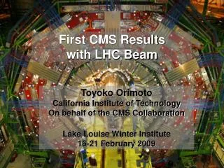
Approved Plots from CMS First Beam Runs 2-October-2008
First Events: Beam going through CMS Beam Pickup (ch1) CMS Beam Condition Monitors (ch 3, 4) First Beam Results
Sep 10 - first multiple orbits orbit signals BPTX First Beam Results
Pictures from Sept.10 – First Beams through CMS Point 5 Control Room CMS Centre Meyrin First Beam Results
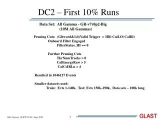
Different projections of a splash event ~2x10⁹ protons on collimator ~150 m upstream of CMS HCAL energy ECAL energy debris DT muon chamber hits Inner tracking systems kept OFF First Beam Results
ECAL Energy from Splash Event ECAL beam splash event from Sept. 10, 2008. White areas in ECAL barrel are trigger towers masked from the readout. The ECAL endcaps are uncalibrated (lowest gain photodetectors are nearest the beam pipe) First Beam Results
Correlation between the total energy deposit in ECAL and in the beam loss monitoring detectors. The diagram shows the location of the beam loss monitors next to the collimators. TCTH TCTV TCLP TAN MBRC CMS 146 m First Beam Results
Distribution of equivalent energy across the CMS Hadron Calorimeters in a beam-on-collimator event during September 2008. This plot has been not been adjusted for cross-sectional area effects, which produce the structures seen at || = 2.8. Uncorrected HCAL Energy from Collimator Event First Beam Results
Corrected HCAL Energy from Collimator Event Distribution of equivalent energy across the CMS Hadron Calorimeters in a beam-on-collimator event during September 2008. In this plot, the reported energy has been corrected for the cross-sectional area of each tower in the endcap and for the length of scintillator in the barrel. First Beam Results
Correlation between reconstructed energy in the CMS Hadron Barrel Calorimeter (HB) and Electron Barrel Calorimeter (EB) for beam-on-collimator events in September 2008. The large reconstructed energy values are the result of the hundreds of thousands of muons which passed through the detector during each event. Correlation of ECAL and HCAL Barrel First Beam Results
Synchronization of HCAL from Splash Events First Beam Results
This plot shows the difference between predicted pulse arrival time and mean pulse arrival time for the beam-on-collimator events of September 10, 2008. The HCAL barrel uses tuned integration delays in this data, while the other sections of the detector are not tuned. This result combines events from both LHC beams, which cancels several systematic effects. HCAL Splash Delays Before Tuning First Beam Results
This plot shows the difference between predicted pulse arrival time and mean pulse arrival time for the beam-on-collimator events of September 18, 2008. This data set uses delays tuned from the previous beam-on-collimator runs, except for a small region of the outer hadron calorimeter which has since been corrected. This result uses events from only a single beam of LHC and some residual systematic effects are present. HCAL Splash Delays After Tuning First Beam Results
This plot shows the difference between predicted pulse arrival time and mean pulse arrival time for the beam-on-collimator events of September 18, 2008. This data set uses delays tuned from the previous beam-on-collimator runs, except for a small region of the outer hadron calorimeter which has been omitted in this plot. This result uses events from only a single beam of LHC and some residual systematic effects are present. HCAL Splash Delays After Tuning and HO partly removed First Beam Results
These figures show the distribution of energy observed in the CMS Endcap Hadron Calorimeter before and after capture of the LHC by the RF system. Before beam capture the high rate of energy deposit near the beamline is quite clear, while the beam after capture is quite clean. HCAL Endcap Energy Before/After Capture First Beam Results
Average energy as a function of eta in the CMS Forward Hadron Calorimeter (HF) for circulating beam events at LHC. The events in question are triggered by the HF from LHC's Beam 2, which passes through the CMS Detector from negative to positive z. The events further selected to contain at least one deposit of 20 GeV in a tower which is registered by both the long and short fiber sections of the tower. These sections measure the total energy and the hadronic energy of a shower, respectively. The peak in energy deposition towards positive pseudorapidity is a signature of beam-gas interactions near or within the detector, as the remnants of beam-gas interactions will have a small transverse momentum and a larger longitudinal momentum from the initiating proton. Evidence for Beam Gas Collisions in HF Energy First Beam Results
Linearity of the number of hits in the third ring of DT chambers vs. total ECAL energy for splash events Muon chambers or calorimeter? First Beam Results
Three muons are reconstructed in the Cathode Strip Chambers (CSC's). The chambers with hits are shown as trapezoidal volumes in white, with yellow strips running in the radial direction, and purple wires running in the azimuthal direction. The long blue lines threading several chambers represent muon trajectories reconstructed offline. One line appears to be bent due to multiple scattering of the muon in the calorimeter. This particular beam halo / beam gas event is unusual in having three reconstructed muons; most events have one. Beam Halo Muons Reconstructed in CSCs First Beam Results
Single and double halo muon events CSC Halo Muons First Beam Results
CSC and DT Halo Muon Event First Beam Results
Halo muon observed traversing between both CSC endcaps and leaving a pattern of energy in the barrel hadron calorimeter X-Y projection on next page CSC – HCAL halo muon First Beam Results
This is an XY view of the hadronic calorimeter showing a large measured energy due to a beam muon which was tracked in the CSC's. The muon is coming out of the page. The strips (green) and wires (purple) which register the incoming muon are also displayed. The muon is coming in at an angle, so the intersection point of the strips and wires does not line up with the tower, which has 7.6 GeV. CSC – HCAL Halo Muon First Beam Results
Halo muon observed traversing between both CSC endcaps and leaving a pattern of energy in the barrel hadron calorimeter X-Y projection on next page CSC – HCAL Halo Muon First Beam Results
This is an XY view of the hadronic calorimeter showing a large measured energy due to a beam muon which was tracked in the CSC's. The muon is coming out of the page. The CSC strips (green) and wires (purple) which register the incoming muon are also displayed. In this event, the intersection point of the strips and wires line up nicely with the calorimeter tower, which has an energy of 4.3 GeV. CSC – HCAL Halo Muon First Beam Results
This plot shows the distribution of the angles of reconstructed muon tracks with respect to the plane perpendicular to the beam. One expects beam halo muons to make a small angle, and this is illustrated by the blue histogram. In contrast, muons from cosmic rays should pass through the cathode strip chambers at a more oblique angle, and this is what we see when the beam is off (black histogram). When the beam is on (orange-shaded histogram) the distribution consists of two pieces, one of which closely resembles cosmic rays, and the other which matches the beam halo simulation. The normalization of the blue and black histograms are not based on any calculation; they are meant to guide the eye. Halo and Cosmic Muon Angles First Beam Results
ME1 ME2 ME3 ME4 ME+1 ME+2 ME+3 ME+4 Beam Halo Hit Distribution Arrow indicates order beam traversed endcap disks First Beam Results
This plot shows the CSC halo trigger rate in the MINUS endcap as a function of time. The yellowish band indicates the first successful RF capture of the LHC beam (beam 2) which lasted about 10min (and ended with the first automatic beam abort). One sees rate jumps preceding this due to earlier capture attempts. These rates are defined by averaging over a 10 s interval. Sectors 1 and 6 are mostly horizontal on the inside part of the ring Online CSC Halo Muon Rates during LHC Beam Capture First Beam Results